57 Installation and Service Guide
Replacing Parts
1 Insert the printer interface board into the PCIE x16 slot (the top slot) on the motherboard, and then secure it to the
chassis with the board mounting bracket screws that you removed earlier.
The printer interface board edge connector is keyed to fit in the motherboard connector only when properly
oriented.
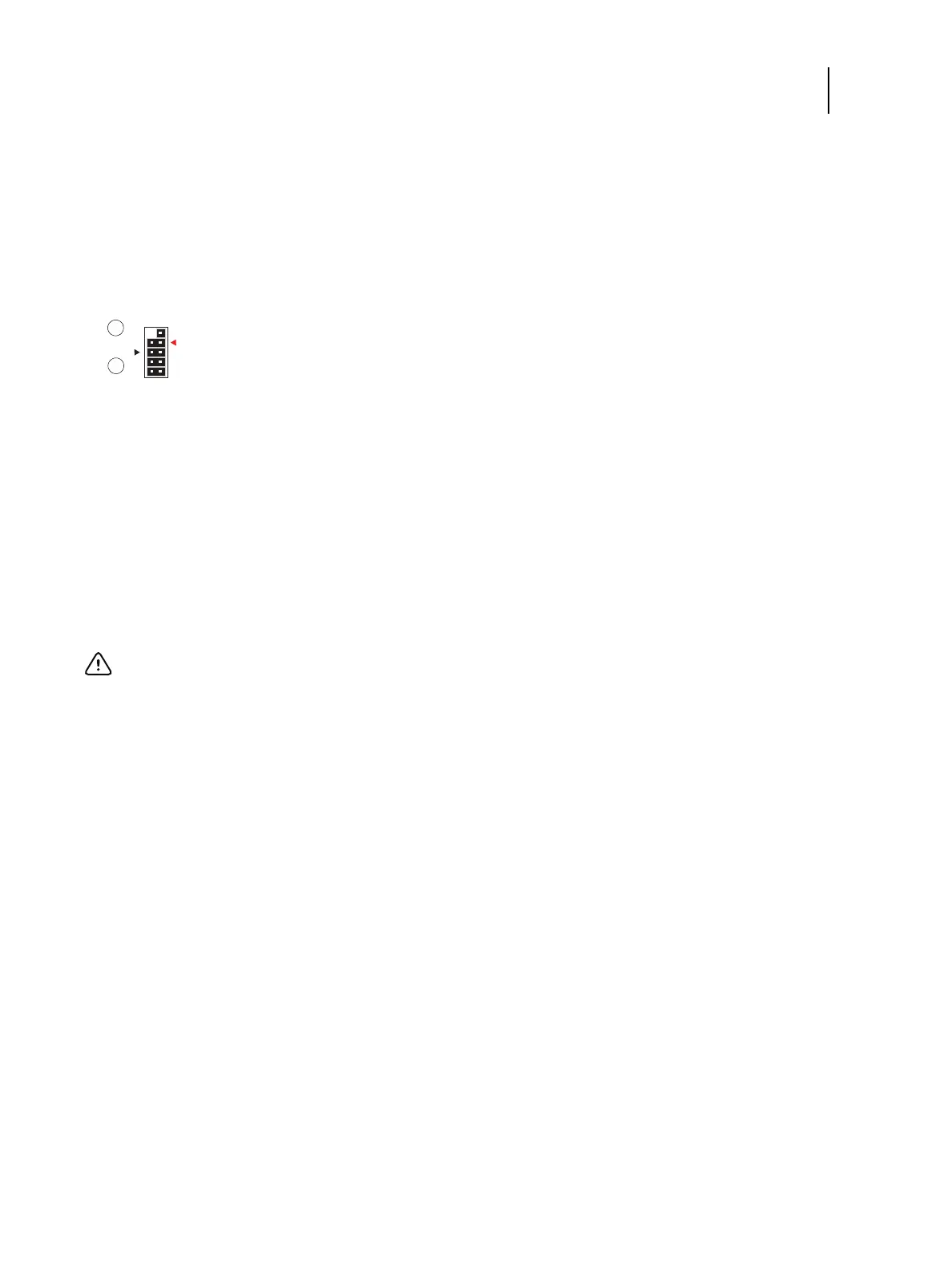
2 Connect the LED/SW cable from the Fiery QuickTouch to the J102 connector (see Figure 30).
Figure 30: J102 connector on the printer interface board
3 Connect the 10-pin power button cable from the FP HDR connector (J11) on motherboard to the J103 connector
on the printer interface board (see Figure 29 on page 56).
4 Replace the cover mounted at rear side of the chassis.
5 Reassemble the E-35A and verify its functionality (see page 82).
Motherboard
The CPU mounted on the motherboard controls the image data transferred to and from the printer interface board.
The motherboard also controls hard disk drive functions and the communication between the E-35A and external
devices.
1 SW LED cable connection
2 SW cable connection
Important: If you are removing the motherboard in order to replace it with a new motherboard, review the
troubleshooting and motherboard cautions on page 61.
Align triangle on cable connector as shown.
SW LED
SW
(Black/Red)
(Red/Yellow)
12
910

 Loading...
