54 Installation and Service Guide
Replacing Parts
d Remove the screw holding the bracket to the Fiery QuickTouch.
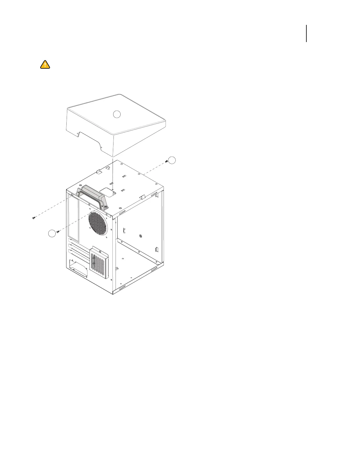
Figure 28: Removing/replacing the Fiery QuickTouch
3 Remove the front panel (see page 51).
4 Remove the front screw holding the front side of the Fiery QuickTouch.
5 Remove the two rear screws holding the rear side of the Fiery QuickTouch.
6 Lift the Fiery QuickTouch away from the chassis.
Replace the Fiery QuickTouch
1 Align the power harness and USB connectors located under the Fiery QuickTouch to the connectors hole on top of
the chassis.
2 Place the Fiery QuickTouch on top of the chassis.
Caution:Use a screwdriver with a magnetic tip so you do not drop the screw into the Color Controller E-
35A.
1 Fiery QuickTouch 3 Screws, rear side (x2)
2 Screw, front side

 Loading...
