FLEX-6000 Signature Series – Maestro User Guide
Page 95
Copyright 2019 FlexRadio Systems. All Rights Reserved.
In the image above, a FLEX-6700 is configured so that the Slice A receive antenna is set to RX A and
the Slice B antenna to RX B. ANT1 is selected as the transmit antenna for Slice A and ANT2 for Slice
B. This configuration allows separate receive antennas on the two independent SCUs. This
configuration is not available on the single SCU FLEX-6500 or FLEX-6300.
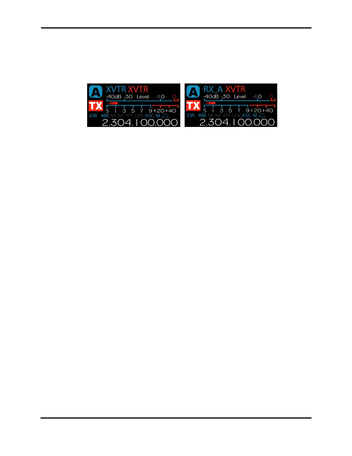
22.8 ANTENNA SELECTION FOR TRANSVERTER OPERATION
The Slice Flag shown above on the left shows XVTR selected for both receive and transmit antennas.
This provides typical transverter port transceiver operation. The Slice Flag on the right illustrates the
configuration in which RX A is set as the receive antenna and XVTR as the transmit antenna. This
configuration supports split transmit/receive transverter operation.
 Loading...