FLEX-6000 Signature Series – Maestro User Guide
Page 11
Copyright 2019 FlexRadio Systems. All Rights Reserved.
4.4.8 Mic 1 Connector
The 8-pin RJ-45 MIC 1 connector offers the ability to connect a microphone and to key the radio via
a PTT line. The RJ-45 pin-out is shown below. To engage PTT, pin 6 must be grounded to pin 7 (Shield
Ground) and not to pin 4, which is the microphone ground.
To prevent ground loops and RF ingress into the microphone circuit, the MIC (-) wire should be
connected to pin-4 only and NOT be connected to the pin-7 chassis ground. The microphone circuit
is wired as pseudo-differential and can thus be used with balanced or unbalanced microphones so
long as the MIC (-) wire connects only to pin-4. Bias for electret microphones may be derived from
the +5 VDC output on pin-3.
Although Maestro will work well with many types of microphones, it is wired for the convenient use
of microphones such as the FlexRadio FMH-1-RJ45. The FHM-1-8P hand microphone supplied with
the FLEX-6000 Series Radios uses an 8-pin Foster connector. This microphone may be adapted to
Maestro with either the ACC-ADM817 RJ45 to 8-pin Male Foster Adapter cable or the ACC-CLV-310
RJ45 to RJ45 coiled cable replacement.
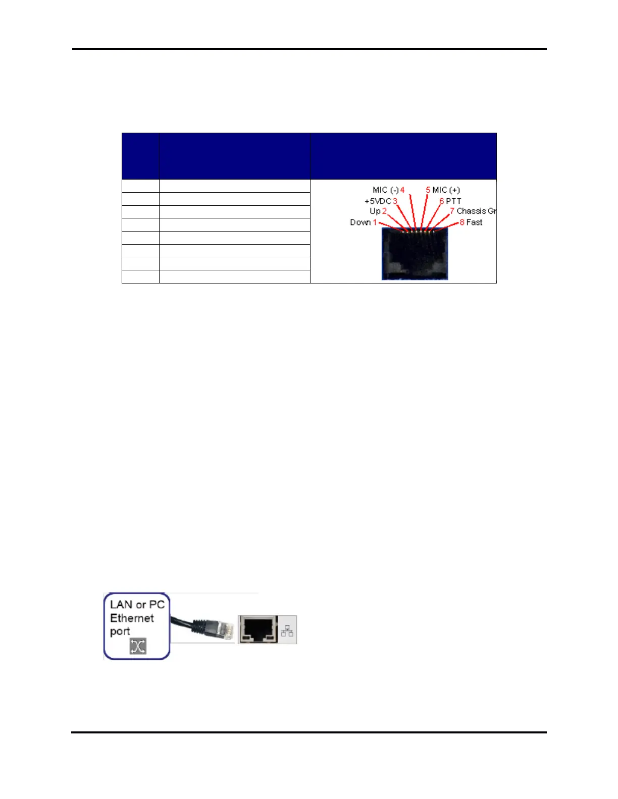
4.4.9 Ethernet Connector
To use wired Ethernet communications, connect the included CAT5 Ethernet cable from the RJ-45
connector marked with the network symbol as shown below. The connector is located above the 10-
15 VDC power connector on the left side of the Maestro back panel. Be careful not to plug the
Ethernet cable into the MIC 1 connector located on the rear right side of the back panel.
 Loading...