Table
5-1.
Sample Rates and Reading Rates
I
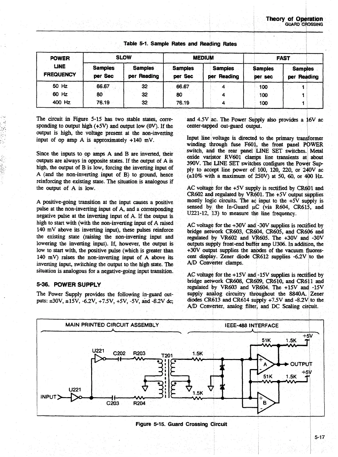
The circuit
in
Figure 5-15 has two stable states, corre-
and 4.5V ac. The Power Supply
also
provides a
sponding to output high (+5V) and output low (OV). If the
center-tapped out-guard output.
output is high, the voltage present
at
the non-inverting
input of op amp
A
is approximately +I40
mV.
Input line voltage
is
directed to the
winding through
fuse
F601, the front
Since
the inputs to op
amps
A
and
B
are
inverted, their
oxide
outputs are always in opposite states. If the output of
A
is
390~.
high, the output of
B
is low, forcing the inverting input of
ply
to
reinforcing the existing state. The situation is analogous if
the output of
A
is low.
A
(and the non-inverting input of
3)
to ground, hence
(*lo% with a maximum of
250~)
at
50,
60,
or
9
k.
AC voltage for the +SV supply is rectified by
CR+~
and
CR602
and
regulated by VR601. The +5V output
s
pplies
A
pitive-going transition at
he
input -es
a
positive
1110Btly lo@ circuits. The ac input to the
i-N
SU~&
is
pulse at the non-inverting input of
A,
and a corresponding
sensed
by
the In-Guard
CIC
(via R604, CR61$, and
negative pulse at the inverting input of
A.
If the output is
U221-12,
13)
to measure thk line frequency.
I
high to start with (with the non-inverting input of
A
raised
AC
140
mV
above its inverting input), these pulses reinforce
the existing state (raising the non-inverting input
and
lowering
the
inverting input). If, however, the output is
low to
start
with,
the
positive pulse (which is greater than
140
mV)
raises the non-hming input
of
A
above its
inverting input, switching the output to the
high
state. The
AfD
Converter
situation is analogous for
a
negative-going input transition.
AC voltage for the +15V and -15V supplies is
5-36.
POWER
SUPPLY
bridge nework CR608, CR-, CR610,
and
The Power Supply provides the following in-guard out-
puts: dOV, .c15V, -6.2V, +7.5V7 +5V,
-5V,
and
-8SV
dc;
&odes
I
POWER
LINE
FREQUENCY
50
Hz
60Hz
400t-k
MAIN PRINTED CIRCUIT ASSEMBLY
IEEE-488
l
NTERFACE
,
A
A
\
/
+5
INPUT
Fqure
5-15.
Guard Crossing dircuit
SLOW
Samples
per Sec
66.67
80
76.19
Samples
per
Reading
32
32
32
MEDlUP
I
FAST
I
Samples
per
Sec
66.67
80
76.19
Samples
yr
Reading
4
4
4
ding
Samples
per
sec
Samples
per
Res
100
100
100
1
(
1
I
1
I
Artisan Technology Group - Quality Instrumentation ... Guaranteed | (888) 88-SOURCE | www.artisantg.com

 Loading...


