Operating Instructions
OPERATING
FEATURES
I
FOR THIS LINE USE THIS SWITCH FOR THIS LINE USE
7
VOLTAGE: SETTING: VOLTAGE: SETTI
'HIS SWITCH
NG:
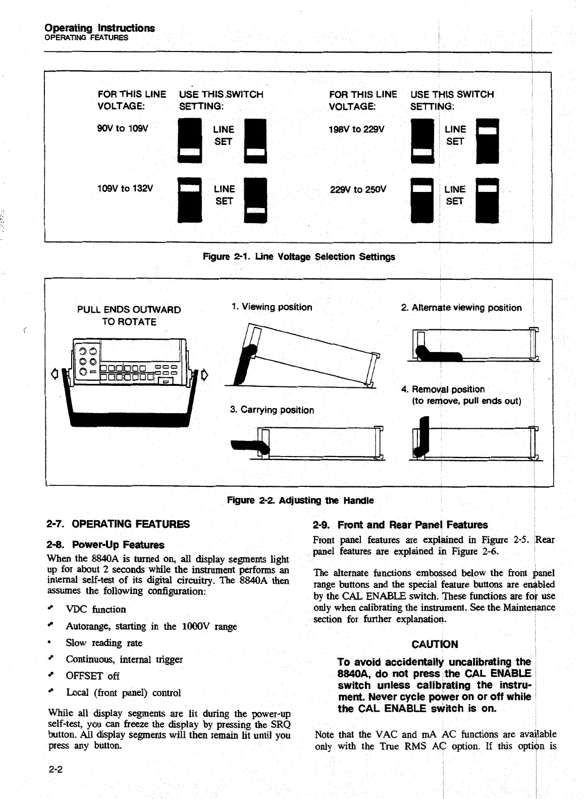
Figure
2-1.
Line Voltage Selection Settings
PULL ENDS OUTWARD
TO ROTATE
1.
Viewing position
3.
Carrying position
2.
Alternate viewing position
4.
Remoyal position
(to reflove, pull ends out)
Figure
2-2
Adjusting
the
Handle
2-7.
OPERATING
FEATURES
2-9.
Front
and Rear Panel Features
2-8.
Power-Up Features
Front panel features are explained in Figure
2-5.
Rear
panel features are explained in Figure
2-6.
When the
8840A
is turned on,
all
display segments light
up
for
about
*
while
the
instrument
prfoms
an
The
alternate functions embossed below the front banel
internal self-tat of its digital circuitry. The
8840A
then
range
bunons
and
the
special
faoure
bunons
are
en.+bld
assumes the following configuration:
by the
CAL
ENABLE
switch. These
functions
are for use
VDC
function
Autorange, starting in the
lOOOV
range
ohy when calibrating the instrument. See the ~ainteiance
section for further explanation.
Slow reading rate
CAUTION
Continuous, internal trigger
To avoid accidentally uncalibrating
OFFSET
off
8840A. do not press the CAL ENA
Local
(front panel) control
switch unless 'calibrating the instru-
,
rnent. Never cycle wwer on or off while
While
all
display segments are lit during the power-up
the
CAL
ENABLE
'sditch is on.
self-test, you
can
freeze the display by pressing the SRQ
button. All display segments will then remain lit until you
Note that the
VAC
and
rnA
AC
functions are avdflable
press
any
button.
only
with the True
RMS
AC
option. If
this
opti$n is
Artisan Technology Group - Quality Instrumentation ... Guaranteed | (888) 88-SOURCE | www.artisantg.com

 Loading...


