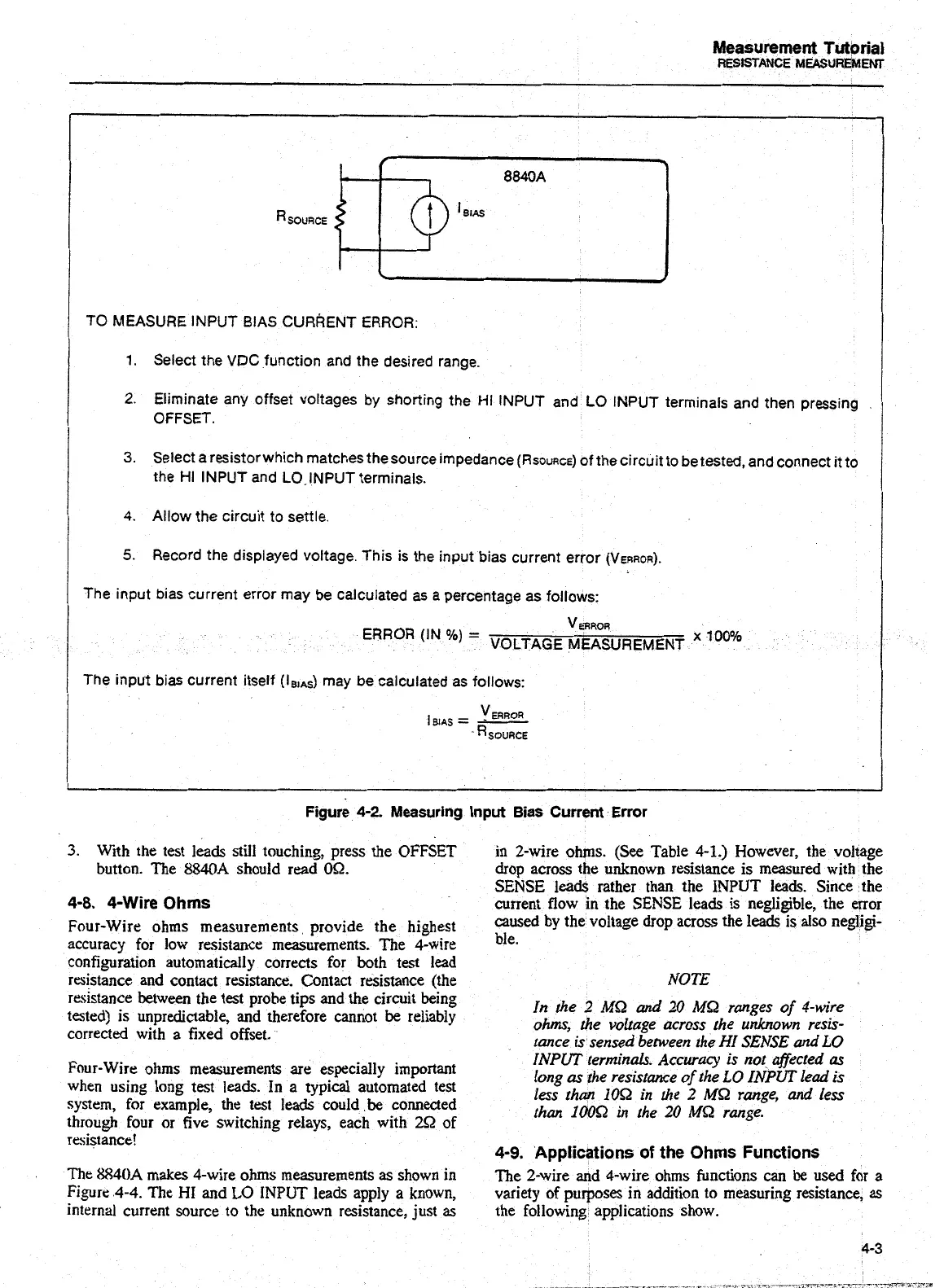
TO MEASURE INPUT BIAS
CURRENT
ERROR:
/
1. Select the VDC function and the desired range.
2.
Eliminate any offset voltages by shorting the HI INPUT and LO INPUT terminals and then pressing
OFFSET.
3.
Select a resistorwhich matches the source impedance
(RSOURCE)
of the circuit to be tested. and connect it to
the HI INPUT and LO-INPUT terminals.
Measurement
Tutorial
RESISTANCE
MEASUREMEW
I
-
4.
Allow the circuit to settle.
5.
Record the displayed voltage. This is the input bias current error (VERROR).
I
The input bias current error may be calculated
as
a percentage as follows:
ERROR
(IN
%)
=
VERROR
VOLTAGE MEASUREMENT
x
100%
The input bias current itself (I,,,,) may be calculated as follows:
Figure
4-2
Measuring
input
Bias Current Error
3.
With the test leads still touching, press the OFFSET
in 2-wire ohms. (See Table 4-1.) However, the voltage
button. The
8840A
should read
09.
drop across the unknown resistance is measured with the
SENSE leads rather than the INPUT leads, Since the
4-8. 4-Wire
Ohms
current flow in the SENSE leads is negligible, the error
Four-Wire ohms measurements provide the highest
caed
the
voltage across
the
leads
is negligi-
accuracy for low resistance measurements. The 4-wire
ble.
configuration automatically corrects for both test lead
resistance and contact resistance. Contact resistance (the
NOTE
resistance
between the test prohe tips and the circuit being
tested) is unpredictable, and therefore cannot
be
reliably
In the 2
MQ
and 20
MQ
ranges of 4-wire
corrected with a fixed offset.
ohms, the voltage across the unknown resis-
tance is sensed between the
HI
SENSE and
LO
Four-Wire ohms measurements are especially important
INPUT
terminals. Accuracy is
no1
affected
a~
when using long test
leads.
In a typical automated test
long
a.
the resistance of the
LO
INPUT
lead is
system, for example, the test leads could be connected
less than 108 in the
2
M8 range,
and
less
through four or five switching relays, each with
29
of
than 10052 in fhe
20
MQ
range.
resistance!
4-9.
Applications
of
the
Ohms Functions
The 8840A makes 4-wire ohms measurements
as
shown in
The 2-wire and 4-wire ohms functions can
be
used for a
Figure 4-4. The
HI
and
LO
INPUT leads apply a known, variety of purposes in addition to measuring resistance,
as
internal current source to the unknown resistance, just
as
the following applications show.
4-3
Artisan Technology Group - Quality Instrumentation ... Guaranteed | (888) 88-SOURCE | www.artisantg.com

 Loading...


