Maintenance
TROUBLESHOOTING
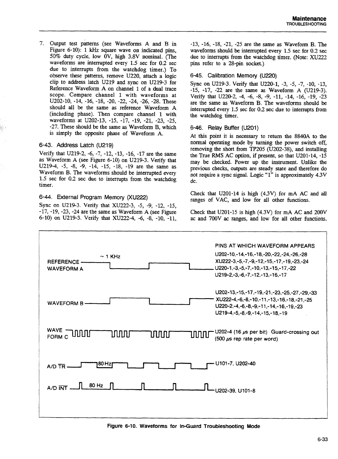
7.
Output test (see Waveforms
A
and
B
in
Figure 6-10):
1
kHz
square wave on indicated pins,
50% duty cycle, low OV, high 3.8V nominal. (The
waveforms are interrupted every 1.5 sec for 0.2 sec
due to interrupts from the watchdog timer.) To
observe these patterns, remove U220, attach a logic
clip to address latch U219 and sync on U219-3 for
Reference Waveform
A
on channel
1
of
a
dual trace
scope. Compare channel
1
with waveforms
at
U202-10, -14, -16, -18, -20,
-22,
-24, -26, -28. These
should all
be
the same
as
reference Waveform A
(including phase). Then compare channel
1
with
waveforms at U202-13, -15, -17, -19, -21, -23, -25,
-27. These should be the same
as
Waveform B, which
is simply the opposite phase of Waveform A.
6-43.
Address
Latch
(U219)
Verify that U219-2, -6,
-7,
-12, -13, -16, -17 are the same
as Waveform
A
(see Figure 6-10) on U219-3. Verify that
U219-4,
-5,
-8,
-9, -14, -15, -18, -19 are the same
as
Waveform B. The waveforms should be interrupted every
1.5 sec for 0.2 sec due to interrupts from the watchdog
timer.
6-44.
External Program
Memory
(XU222)
Sync
on
U219-3. Verify that XU222-3, -5,
-9,
-12, -15,
-17, -19,
-23,
-24 are the same as Waveform
A
(see Figure
6-10) on U219-3. Verify that XU222-4, -6,
-8,
-10, -11,
-13, -16, -18, -21, -25 are the same
as
Waveform B. The
waveforms should
be
interrupted every 1.5 sec for 0.2 see
the to interrupts from the watchdog timer. (Note: XU222
pins refer to
a
28-pin socket.)
6-45.
Calibration
Memory
(U220)
Sync on U219-3. Verify that U220-1, -3,
-5,
-7,
-10, -13,
-15, -17, -22 are the same as Waveform A (U219-3).
Verify that U220-2, -4, -6, -8, -9,
-11,
-14, -16, -19, -23
are the same
as
Waveform B. The waveforms should
be
interrupted every 1.5 sec for 0.2 sec due to interrupts from
the watchdog timer.
6-46.
Relay
Buffer
(U201)
At this point it is necessary to return the 8840A to the
normal operating mode
by
turning the power switch off,
removing the short from TP205 (U202-38), and installing
the True RMS AC option, if present, so that U201-14, -15
may be checked. Power up the instrument. Unlike the
previous checks, outputs are steady state and therefore do
not require a sync signal. Logic
"1"
is approximately 4.3V
dc.
Check that U201-14 is high (4.3V) for mA AC and all
ranges of VAC, and low for
all
other functions.
Check that U201-15 is
high
(4.3V) for mA AC and 200V
ac and 700V
ac
ranges, and low for
all
other functions.
PINS AT WHICH WAVEFORM APPEARS
-
1
KHz
U202-10,-14,-16.-18.-20,-22,-24,-26,-28
REFERENCE
XU222-3,-5,-7.-9,-12,-15,-17,-19,-23,-24
-1-
U220-1.-3.-5.-7.-10,-13,-1597.-22
WAVEFORM
A
U219-2,-3,-6,-7,-12.-13,-16,-17
WAVE
UUUU
UmU202-4 (16
ps
per
bit) Guard-crossing out
FORM
Cm
(500
psi
rep rate per
word)
Figure 6-10. Waveforms for In-Guard Troubleshooting Mode
6-33
Artisan Technology Group - Quality Instrumentation ... Guaranteed | (888) 88-SOURCE | www.artisantg.com

 Loading...


