Maintenance
TROUBLESHOOTING
2.
Release the two nylon latches that hold the
IEEE-488
CAUTION
Interface
PCA
in place by pulling the latches upward.
To
avoid damage to the
8840A
or other
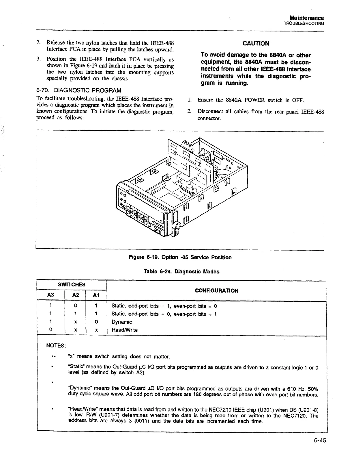
3.
Position the
IEEE-488
Interface
PCA
vertically
as
equipment, the
8840A
must be discon-
shown in Figure
6-19
and latch it in place
be
pressing
the two nylon latches into the mounting supports
nected from all other
IEEE-488
interface
specially provided on the chassis.
instruments while the diagnostic pro-
gram is running.
6-70.
DIAGNOSTIC
PROGRAM
To facilitate troubleshooting, the
IEEE-488
Interface
pro-
1.
Ensure the
8840A
POWER switch is
OFF.
vides a diagnostic program which places the instrument
in
known configurations. To initiate the diagnostic program,
2.
Disconnect all cables from the
rear
panel
IEEE-488
-
-
-
proceed as follows: connector.
r
-
1
-
Figure
649.
Option
-05
Service
Position
Table
6-24.
Diagnostic
Modes
CONFIGURATION
SWITCHES
Static, odd-port bits
=
1, even-port bits
=
0
Static, odd-port bits
=
0, even-port bits
=
1
0
X
-
-
NOTES:
"x"
means switch setting does nol: matter
"Static" means the Out-Guard
WC
VO
port
bits programmed as outputs are driven to
a
constant logic 1
car
0
level (as defined by switch
A2).
"Dynamicw means the Out-Guard
PC
110 port bis programmed as outputs are driven with a 610
Hz,
50%
duty cycle square wave. All odd
port
bi
numbers are 180 degrees out of phase with even
port
bi
numbers.
"ReadNVriten means that data is read from and wriien to the NEC7210 IEEE chip
(U901)
when
DS
(U901-8)
is low.
FUW (U901-7) determines whether the data is being read from or written to the NEC7120. The
address
bits
are
always
3
(0011) and the data bits are incremented each time.
Artisan Technology Group - Quality Instrumentation ... Guaranteed | (888) 88-SOURCE | www.artisantg.com

 Loading...


