Measurement
Tutorial
AC
VOLTAGE
AND
CURRENT
MEASUREMENT
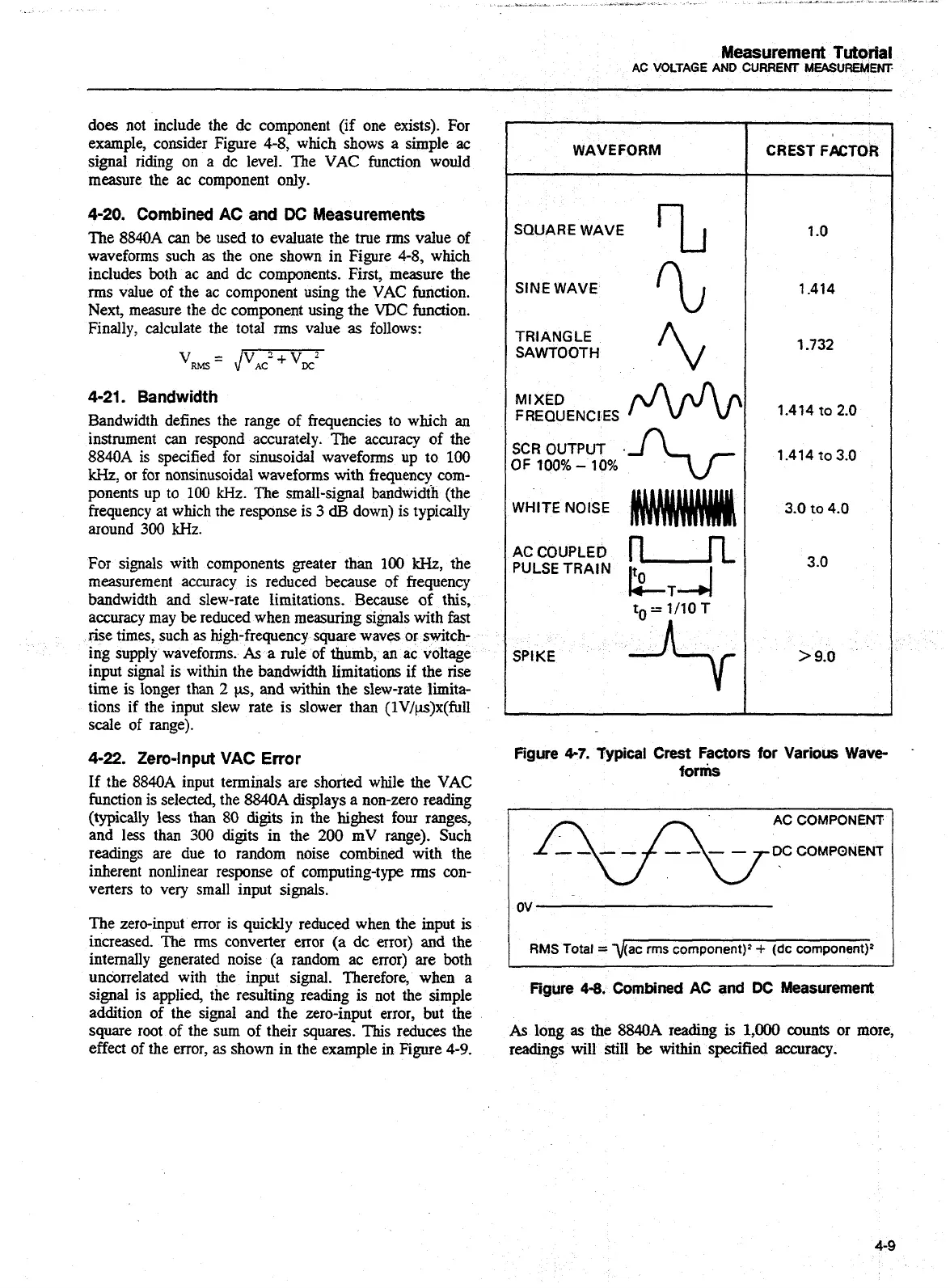
does not include the dc component (if one exists). For
example, consider Figure
4-8,
which shows a simple
ac
signal riding on a dc level. The VAC function would
measure the ac component only.
4-20.
Combined
AC
and
DC
Measurements
The
8840A
can
be
used to evaluate the true rms value of
waveforms such
as
the one shown in Figure
4-8,
which
includes both ac and dc components. First, measure the
rrns value of the ac component using the VAC function.
Next, measure the dc component using the
VDC
function.
Finally, calculate the total rms value
as
follows:
4-21.
Bandwidth
Bandwidth defines the range of frequencies to which
an
instrument
can
respond accurately. The accuracy of the
8840A
is specified for sinusoidal waveforms up to
100
kHz,
or for nonsinusoidal waveforms with frequency com-
ponents up to
100
kHz. The small-signal bandwidth (the
frequency at which the response is
3
dB
down) is typically
around
300
kHz.
For signals with components greater than
100
kHz,
the
measurement accuracy is reduced because of frequency
bandwidth
and
slew-rate limitations. Because
of
this,
accuracy may
be
reduced when measuring signals with fast
rise times, such as high-frequency square waves or switch-
ing supply waveforms.
As
a rule of thumb, an ac voltage
input signal is within the bandwidth limitations if the rise
time is longer than
2
w,
and within the slew-rate limita-
tions
if
the input slew rate is slower than (lV/p.)x(full
scale of range).
4-22.
Zero-Input
VAC
Error
If the
8840A
input terminals are shorted while the VAC
function is selected, the
8840A
displays a non-zero reading
(typically less than
80
digits in the highest four ranges,
and less than
300
digits in the
200
mV range). Such
readings
are
due to random noise combined with the
inherent nonlinear response of computing-type rms
con-
verters to very small input signals.
The zero-input error is quickly reduced when the input is
increased. The rms converter error (a dc error)
and
the
internally generated noise
(a
random ac error) are both
uncorrelated with the input signal. Therefore, when a
signal is applied, the resulting reading is not the simple
addition of the signal and the zero-input error, but the
square root of the sum of their
squares.
This reduces the
effect of the error,
as
shown in the example in Figure
4-9.
WAVEFORM
SQUARE WAVE
Z
SINE WAVE
'L
TRIANGLE
SAWTOOTH
MIXED
FREQUENCIES
SCR
OUTPUT
.
OF
100%
-
10%
%-
WHITE NOISE
ACCOUPLED
PULSE TRAIN
LT-4
SPl
KE
CREST FACTOR
Figure
4-7.
Typical
Crest
Factors
for
Various Wave
forms
AC
COMPONENT
DC COMPONENT
RMS
Total
=
Figure
4-8.
Combined
AC
and
DC
Measurement
As
long
as
the
8840A
reading
is
1,000
counts or more,
readings
will
still be witbin specified accuracy.
Artisan Technology Group - Quality Instrumentation ... Guaranteed | (888) 88-SOURCE | www.artisantg.com

 Loading...


