Theory
of
Operatiion
DC
SCALING-
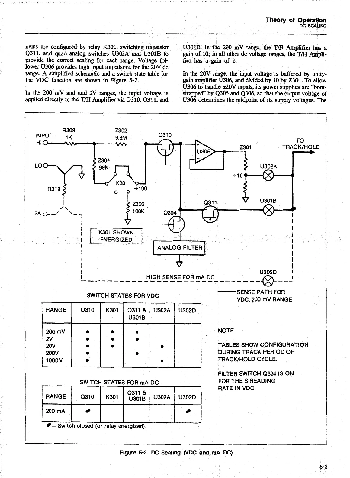
nents are configured by relay
K301,
switching transistor
U301B. In the 200 mV range, the T/H Amplifier
has
a
Q311, and quad analog switches U3oZA
and
U30lB to
gain
of 10; in all other dc voltage ranges, the
TB
Ampli-
provide the correct scaling for each range. Voltage fol-
fier
has
a gain of
1.
lower U306 provides high input impedance for the 20V dc
range.
A
simplified schematic and a switch state table for
In
the 20V range, the input voltage
is
buffered by unity-
the
VDC
function are shown in Figure 5-2.
gain amplifier U306, and divided
by
10 bv
2301.
To allow
U306 to
handle
&OV inputsy its power supplies
are
"boot-
In the 200 mV and and
2V
ranges, the input voltage
is
strapped" by Q305 and Q306, so that the output voltage of
applied directly to the
T/H
Amplifier via Q310, Q311, and
U306 determines the midpoint of its supply voltages. The
R309 2302
INPUT 1~
9.9M
031 0
TO
2301 TRACK/HOLD
U302A
s10
Q311 U301
B
t
I
I
I
I
ENERGIZED
I
I
I
ANALOG FILTER
I
SWITCH STATES FOR VDC
RANGE 0310 K301 Q311
&
U302A
U301
B
I
-
SENSE PATH FOR
VDC. 200 mV RANGE
NOTE
TABLES SHOW CONFIGURATION
DURING TRACK PERIOD OF
TRACK/HOLD CYCLE.
FILTER SWITCH
Q304 IS ON
Figure
5-2.
DC
Scaling
(VDC
and
mA
DC)
SWITCH STATES FOR mA DC
FOR THE S READING
RANGE
200
mA
=
Switch
closed (or relay energized).
0310
RATE IN VDC.
K301
",",'dl:
U302A
U302D
Artisan Technology Group - Quality Instrumentation ... Guaranteed | (888) 88-SOURCE | www.artisantg.com

 Loading...


