Maintenance
REASSEMBLY PROCEDURE
A
6.
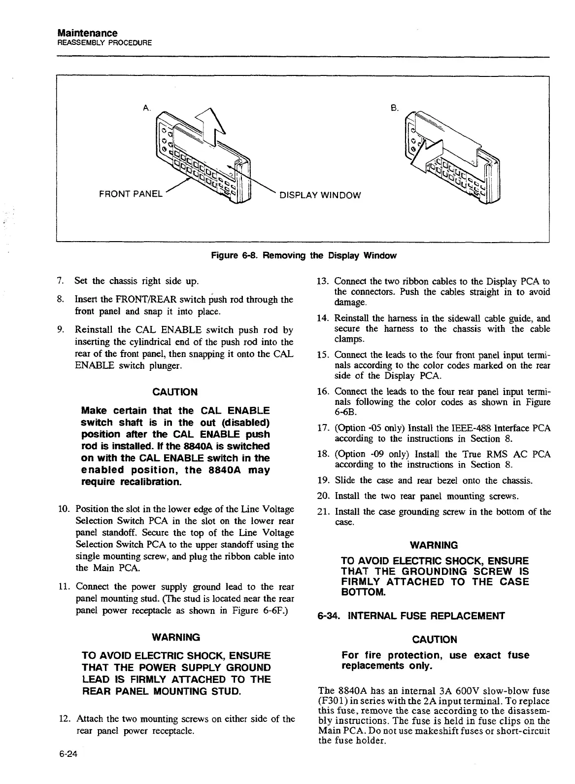
FRONT
PANEL
DISPLAY WINDOW
Figure
6-8.
Removing
the
Display
Window
7.
Set the chassis right side up.
8.
Insert the FRONTREAR switch rod through the
front panel and snap it into place.
9.
Reinstall the CAL
ENABLE
switch push rod by
inserting the cylindrical end of the push rod into the
rear of the front panel, then snapping it onto the CAL
ENABLE switch plunger.
CAUTION
Make certain that the CAL ENABLE
switch shaft is in the out (disabled)
position after the CAL ENABLE push
rod
is
installed.
If
the 8840A is switched
on with the CAL ENABLE switch in the
enabled position, the
8840A
may
require recalibration.
10.
Position the slot in the lower edge of the Line Voltage
Selection Switch PCA in the slot on the lower rear
panel standoff. Secure the top of the Line Voltage
Selection Switch
PCA
to the upper standoff using the
single mounting screw, and plug the ribbon cable into
the Main PCA.
11.
Connect the power supply ground lead to the rear
panel mounting stud. (The stud is located near the rear
panel power receptacle
as
shown in Figure
6-6F.)
WARNING
TO AVOID ELECTRIC SHOCK, ENSURE
THAT THE POWER SUPPLY
GROUNID
LEAD
IS FlRMLY AlTACHED TO
THE
REAR PANEL MOUNTING STUD.
12.
Attach the two mounting screws on either side of the
rear panel power receptacle.
13.
Connect the two ribbon cables to the Display PCA to
the connectors. Push the cables straight in to avoid
damage.
14.
Reinstall the harness
in
the sidewall cable guide, and
secure the harness to the chassis with the cable
clamps.
15.
Comect
the leads to the four front panel input termi-
nals according to the color codes marked on the rear
side of the Display
PCA.
16.
Connect the leads to the four rear panel input termi-
nals following the color codes as shown in Figure
66B.
17.
(Option
-05
only) Install the IEEE-488 Interface PCA
according to the instructions in Section
8.
18.
(Option
-09
only) Install the True
RMS
AC PCA
according to the instructions in Section
8.
19.
Slide the case and rear bezel onto the chassis.
20.
Install the two rear panel mounting screws.
21.
Install the case grounding screw in the bottom of the
case.
WARNING
TO AVOID ELECTRIC SHOCK, ENSURE
THAT THE GROUNDING SCREW
IS
FIRMLY ATTACHED TO THE CASE
BOTTOM.
6-34
INTERNAL FUSE REPLACEMENT
For fire protection, use exact fuse
replacements only.
The
8840A
has an internal
3A 600V
slow-blow fuse
(F301)
in series with the
2A
input terminal. To replace
this
fuse,
remove the case according to the disassem-
bly instructions. The fuse is held in fuse clips on the
Main
PCA.
Do
not
use makeshift fuses or short-circuit
the fuse holder.
Artisan Technology Group - Quality Instrumentation ... Guaranteed | (888) 88-SOURCE | www.artisantg.com

 Loading...


