Maintenance
TROUBLESHOOTING
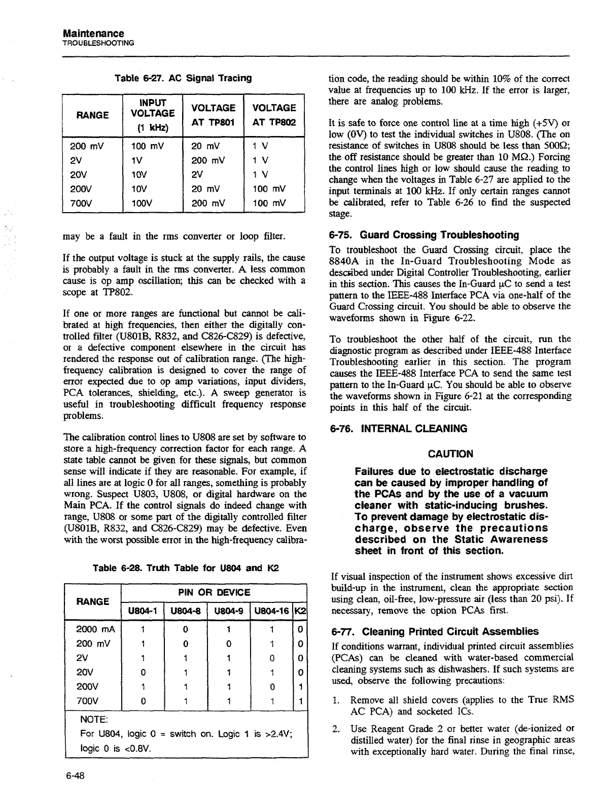
Table
6-27.
AC
Signal Tracing
RANGE
may be a fault in the rms converter or loop filter.
200 mV
2v
20v
200v
700V
If the output voltage is stuck at the supply rails, the cause
is probably a fault in the
rms
converter.
A
less common
cause is op amp oscillation; this can be checked with a
scope at TP802.
INPUT
VOLTAGE
(1
kHz)
If one or more ranges are functional but cannot
be
cali-
brated at high frequencies, then either the digitally con-
trolled filter (U801B7 R832, and C826-C829) is defective,
or a defective component elsewhere in the circuit has
rendered the response out of calibration range. (The high-
frequency calibration is designed to cover the range of
error expected due to op amp variations, iilput dividers,
PCA tolerances, shielding, etc.). A sweep generator is
useful in troubleshooting difficult frequency response
problems.
100 mV
1
v
1
OV
1
ov
1 OOV
The calibration control lines to U808 are set by software to
store a high-frequency correction factor for each range. A
state table cannot be given for these signals, but common
sense will indicate if they are reasonable. For example, if
all lines are at logic 0 for all ranges, something is probably
wrong. Suspect
U803, U808, or digital hardware on the
Main PCA. If the control signals do indeed change with
range,
U808 or some part of the digitally controlled filter
(U801B, R832, and C826-C829) may be defective. Even
with the worst possible error in
the
high-frequency calibra-
VOLTAGE
AT TP801
200 rnv
2v
20
rnv 100 rnv
200 rnV 100 rnV
Table
6-28.
Truth
Table
for
US04
and
K2
VOLTAGE
AT TP802
tion code, the reading should be within 10% of the correct
value at frequencies up to
100
kHz. If the error is larger,
there are analog problems.
RANGE
2000
mA
200 mV
2v
20v
200v
700V
It is safe to force one control line
at
a time high
(+SV)
or
low
(OV)
to test the individual switches in U808. (The on
resistance of switches in U808 should
be
less than
50052;
the off resistance should be greater than 10
MQ.)
Forcing
the control lines high or low should cause the reading to
change when the voltages in Table 6-27 are applied to the
input terminals at 100
kHz.
If only certain ranges cannot
be
calibrated, refer to Table 6-26 to find the suspected
stage.
6-75.
Guard Crossing Troubleshooting
To troubleshoot the Guard Crossing circuit, place the
8840A in the In-Guard Troubleshooting Mode as
described under Digital Controller Troubleshooting, earlier
in this section. This causes the In-Guard
pC
to send
a
test
pattern to the IEEE-488 Interface PCA via one-half sf the
Guard Crossing circuit. You should
be
able to observe the
waveforms shown in Figure 6-22.
NOTE:
For
U804,
logic
0
=
switch
on. Logic
1
is
>2.4V;
logic
0
is
c0.8V.
PIN
OR
DEVICE
To troubleshoot the other half of the circuit,
run
the
diagnostic program
as
described under IEEE-488 Interface
Troubleshooting earlier in this section. The program
causes the
IEEE-488
Interface PCA to send the same test
pattern to the In-Guard
PC.
You should be able to observe
the waveforms shown in Figure 6-21 at the corresponding
points in this half of the circuit.
U804-1
1
1
1
0
1
0
6-76.
INTERNAL CLEANING
CAUTION
U804-8
0
0
1
1
1
1
Failures due to electrostatic discharge
can
be
caused
by
improper handling
of
the PCAs
and
by
the
use of a vacuum
cleaner with static-inducing brushes.
To
prevent damage
by
electrostatic dis-
charge, observe the precautions
described on the Static Awareness
sheet in front of this section.
If visual inspection of the instrument shows excessive dirt
build-up in the instrument, clean the appropriate section
using clean, oil-free, low-pressure air (less than 20 psi). If
necessary, remove the option PCAs first.
U804-9
1
0
1
1
1
1
6-77.
Cleaning Printed Circuit Assemblies
If conditions warrant, individual printed circuit assem.blies
(PCAs)
can
be cleaned with water-based commercial
cleaning systems such
as
dishwashers. If such systems are
used, observe the following precautions:
U804-16
'1
'I
0
,t
0
I
1.
Remove all shield covers (applies to the True
RMS
AC PCA) and socketed ICs.
K2
0
0
0
0
I
1
2. Use Reagent Grade
2
or better water (de-ionized or
distilled water) for the final rinse in geographic areas
with exceptionally hard water. During the final rinse,
Artisan Technology Group - Quality Instrumentation ... Guaranteed | (888) 88-SOURCE | www.artisantg.com

 Loading...


