Maintenance Test
PERFORMANCE
TEST
Ensure the 8840A is on and has warmed up for at least
1
hour.
Select the VDC function.
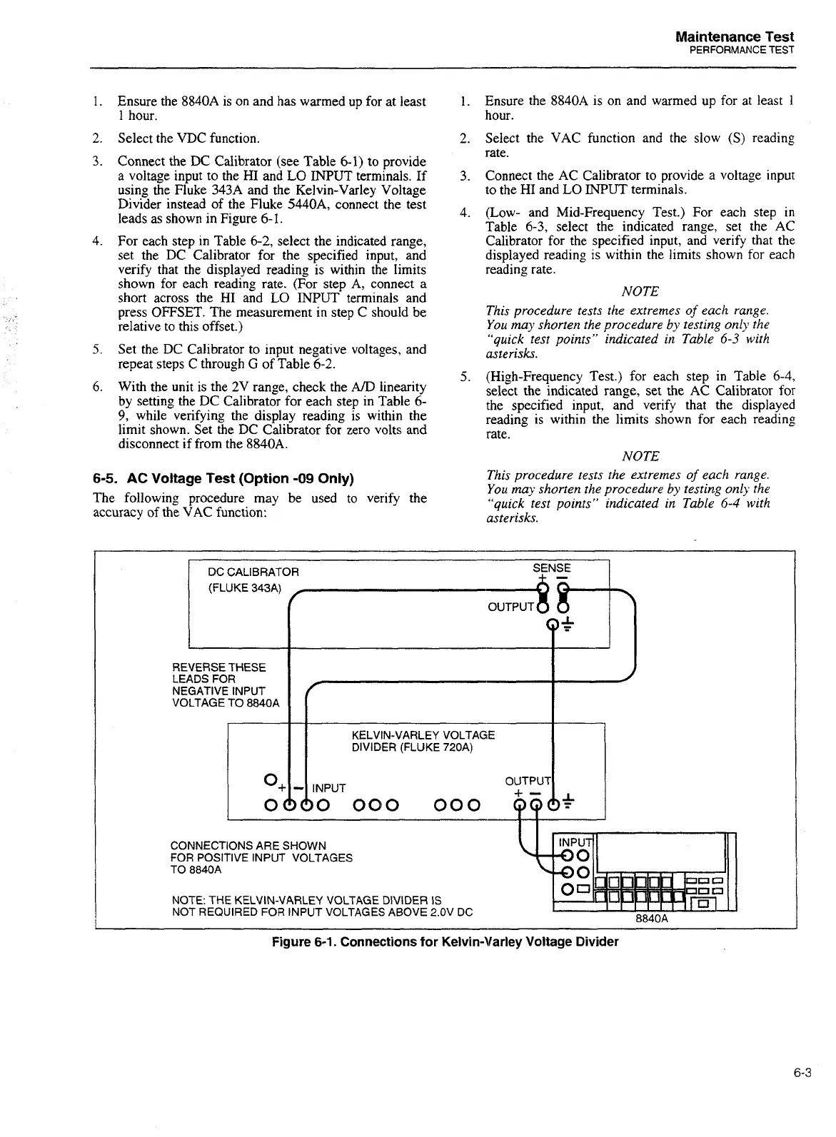
Connect the
DC
Calibrator (see Table 6-1) to provide
a voltage input to the HI and
LO
INPUT
terminals. If
using the Fluke 343A and the Kelvin-Varley Voltage
Divider instead of the Fluke 5440A, connect the test
leads as shown in Figure 6-1.
For each step in Table 6-2, select the indicated range,
set the DC Calibrator for the specified input, and
verify that the displayed reading is within the limits
shown for each reading rate. (For step A, connect a
short across the HI and
LO
INPUT
terminals and
press OFFSET. The measurement in step C should be
relative to this offset.)
Set the DC Calibrator to input negative voltages, and
repeat steps C through
G
of Table
6-2.
With the unit is the 2V range, check the
AID
linearity
by setting the DC Calibrator for each step in Table 6-
9,
while verifying the display reading is within the
limit shown. Set the DC Calibrator for zero volts and
disconnect if from the 8840A.
6-5.
AC
Voltage
Test
(Option
-09
Only)
The following procedure may be used to verify the
accuracy of the
VAC
function:
Ensure the 8840A is on and warmed up for at least
1
hour.
Select the VAC function and the slow
(S)
reading
rate.
Connect the AC Calibrator to provide
a
voltage input
to the HI and LO INPUT terminals.
(Low- and Mid-Frequency Test.) For each step in
Table 6-3, select the indicated range, set the AC
Calibrator for the specified input, and verify that the
displayed reading is within the limits shown for each
reading rate.
NOTE
This procedure tests the extremes of each range.
You may shorten the procedure by testing only the
"quick test points" indicated in Table
6-3
with
asterisks.
(High-Frequency Test.) for each step in Table
6-4,
select the indicated range, set the AC Calibrator for
the specified input, and verify that the displayed
reading is within the limits shown for each reading
rate.
NOTE
This procedure tests the extremes of each range.
You may shorten the procedure by testing only the
"quick test points" indicated
in
Table
6-4
with
asterisks.
DC CALIBRATOR S!NSE
-
(FLUKE 343A)
f--8
t-t-
REVERSE THESE
1
I
LEADS FOR
NEGATIVE INPUT
VOLTAGE TO 8840A
DIVIDER (FLUKE 720A)
OUTPUT
I
3-b~~o~
ooo
ad+
I
CONNECTIONS ARE SHOWN
FOR POSITIVE INPUT VOLTAGES
TO
8840A
NOTE: THE KELVIN-VARLEY VOLTAGE DlVlDER
IS
NOT REQUIRED FOR INPUT VOLTAGES ABOVE 2.OV DC
8840A
-
-
-
Figure
6-1.
Connections for Kelvin-Varley Voltage Divider
Artisan Technology Group - Quality Instrumentation ... Guaranteed | (888) 88-SOURCE | www.artisantg.com

 Loading...


