Maintenance
TROUBLESHOOTING
WAVEFORM NAME
WAVEFORM
PiNS AT
WHICH
WAVEFORM APPEARS
STROBE
585
ps
1
1
U213-4
ZERO
4095
PS
U215-8
STROBE
r
um-5
ONE
4095
ps
U215-7
7
0
1
2
3
4
5
6
7
0
1
U203-9
STROBE
-dlL
U213-6
U215-6
TWO
585
/IS
4095
PS
U203-5
U216-4,
Ezi
ii
-6
an,
,216-9
140
ps
low for inter-digit blanking
450
ps high for data on
through
U
U217-1
through
U217-7
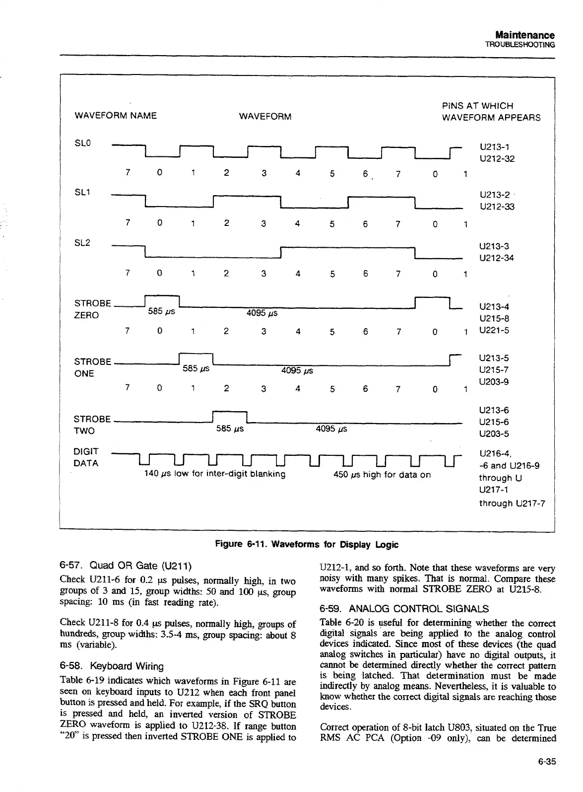
Figure
6-11.
Waveforms for
Display
Logic
6-57.
Quad OR
Gate
(U211)
Check
U211-6
for
0.2
ps
pulses, normally high, in two
groups of
3
and
15,
group widths:
50
and
100
ps,
group
spacing:
10
ms (in fast reading rate).
Check
U211-8
for
0.4
~ls
pulses, normally
high,
groups of
hundreds, group widths: 3.5-4 ms, group spacing: about
8
ms (variable).
6-58.
Keyboard
Wiring
Table
6-19
indicates which waveforms in Figure
6-11
are
seen on keyboard inputs to
U212
when each front panel
button is pressed and held. For example, if the SRQ button
is pressed and held, an inverted version of STROBE
ZERO
waveform is applied to
U212-38.
If range button
"20"
is pressed then inverted STROBE ONE is applied to
U212-1,
and
so
forth. Note that these waveforms are very
noisy with many spikes. That is normal. Compare these
waveforms with normal STROBE ZERO at
U215-8.
6-59.
ANALOG
CONTROL
SIGNALS
Table
6-20
is useful for determining whether the correct
digital signals are being applied to the analog control
devices indicated. Since most of these devices (the quad
analog switches
in particular) have no digital outputs, it
cannot
be
determined directly whether the correct pattern
is being latched. That determination must be made
indirectly
by
analog means. Nevertheless, it is valuable to
know whether the correct digital signals
are
reaching those
devices.
Correct operation of 8-bit latch U803, situated on the True
RMS AC PCA (Option
-09
only), can be determined
Artisan Technology Group - Quality Instrumentation ... Guaranteed | (888) 88-SOURCE | www.artisantg.com

 Loading...


