Maintenance
TROUBLESHOOTING
-
).
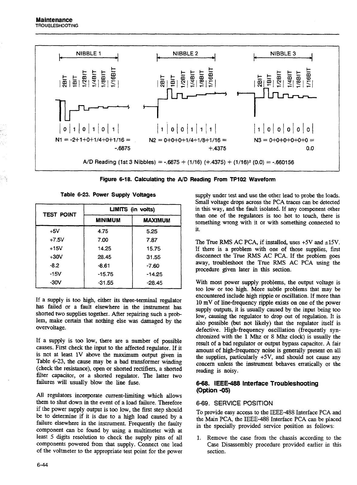
NIBBLE
1
4
I*
4
f.
NIBBLE
2
NIBBLE
3
4
A/D
Reading (1st
3
Nibbles)
:=
-.6875
+
(1/16) (+.4375)
+
(1/16)2 (0.0)
=
-.660156
-
Figure 6-18. Calculating the
AID
Reading
From TP102 Waveform
Table
6-23.
Power Supply Voltages
LIMITS
(in
volts)
TEST
POINT
.
MINIMUM
If a supply is too high, either its threeterminal regulator
has failed or a fault elsewhere in the instrument has
shorted two supplies together. After repairing such a prob-
lem, make certain that nothing else was damaged by the
overvoltage.
If
a
supply is too low, there
are
a
number of possible
causes. First check the input to the affected regulator. If it
is not
at
least
1V
above the maximum output given in
Table
6-23,
the cause may
be
a bad transformer winding
(check the resistance), open or shorted rectifiers,
a
shorted
filter capacitor, or a shorted regulator. The latter two
failures will usually blow the line fuse.
All regulators incorporate current-limiting which allows
them to shut down in the event of a load failure. Therefore
if the power supply output is too low, the first step should
be
to determine if it is due to
a
high load caused by
a
failure elsewhere in the instrument. Frequently the faulty
component
can
be found by using
a
multimeter with at
least
5
digits resolution to check the supply pirs of all
components powered from that supply. Connect one lead
of the voltmeter to the appropriate test point for the power
supply under test and use the other lead to probe the loads.
Small voltage drops across the
PCA
traces can be detected
in this way, and the fault isolated. If any component other
than one of the regulators is too hot to touch, there is
something wrong with it or with something connected to
it.
The True
RMS
AC
PCA,
if
installed, uses
+5V
and
215V.
if
there is a problem with one of those supplies, first
disconnect the True
RMS
AC PCA.
If the problem goes
away, troubleshoot the True
RMS
AC PCA
using the
procedure given later in this section.
With most power supply problems, the output voltage is
too low or too
high.
More subtle problems that may be
encountered include
high
ripple or oscillation. If more than
10
mV of line-frequency ripple exists on one of the power
supply outputs, it is usually caused by the input being too
low, causing the regulator to drop out of regulation. It is
also possible (but not likely) that the regulator itself is
defective. High-frequency oscillation (frequently syn-
chronized with the
1
Mhz
or
8
Mhz
clock) is usually the
result of a bad regulator or output
bypass
capacitor.
A
fair
amount of high-frequency noise is generally present on all
the supplies, particularly
+5V,
and should not cause any
concern unless the instrument behaves erratically
01
the
reading is noisy.
6-68.
IEEE-488 Interface Troubleshooting
(Option
-05)
6-69.
SERVICE
POSITION
To provide easy access to the
IEEE-488
Interface
PCA
and
the Main
PCA,
the
IEEE-488
Interface
PCA
can be placed
in the specially provided service position as follows:
1.
Remove the case from the chassis according to the
Case Disassembly procedure provided earlier in this
section.
Artisan Technology Group - Quality Instrumentation ... Guaranteed | (888) 88-SOURCE | www.artisantg.com

 Loading...


