Maintenance
TROUBLESHOOTING
c
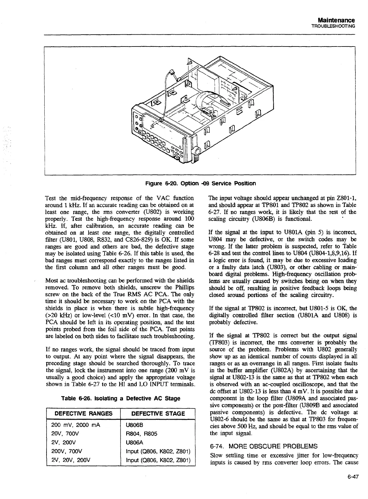
Figure
6-20.
Option
-09
Service
Position
Test the mid-frequency response of the VAC function
around
1
kHz. If
an
accurate reading can be obtained on at
least one range, the rms converter (U802)
is
working
properly. Test the high-frequency response around 100
kHz. If, after calibration, an accurate reading
can
be
obtained on at least one range, the digitally controlled
filter (U801, U808, R832, and C826-829) is
OK.
If some
ranges are good and others are bad, the defective stage
may
be
isolated using Table
6-26.
If this table is used, the
bad ranges must correspond exactly to the ranges listed in
the first column and all other ranges must
be
good.
Most ac troubleshooting
can
be
performed with the shields
removed. To remove both shields, unscrew the Phillips
screw on the back of the True
RMS
AC PCA. The only
time it should
be
necessary to work on the
PC.A
with the
shields in place is when there is subtle high-frequency
(>20
kHz)
or low-level
(<I0
mV)
error. In that case, the
PCA should
be
left in its operating position, and the test
points probed from the foil side of the PCA. Test points
are labeled on
both
sides to facilitate such troubleshooting.
If no ranges work, the signal should
be
traced from input
to output. At any point where the signal
disappears,
the
precedmg stage should be searched thoroughly. To trace
the signal, lock the instrument into one range
(200
mV is
usually a good choice) and apply the appropriate voltage
shown in Table 6-27 to the HI and
LO
INPUT terminals.
Table
6-26.
Isolating
a
Defective AC Stage
DEFECTIVE RANGES
I
DEFECTIVE STAGE
1
-
-
-
-
-
U806B
R804, R805
U806A
Input
(Q806, K802, 2801)
lnput
(Q806, K802,2801)
The input voltage should appear unchanged at pin 2801-1,
and should appear at TE'801 and TP802 as shown in Table
6-27.
If
no ranges work, it is likely that the rest
of
the
scaling circuitry (U806B) is functional.
If the signal
at
the input to U801A (pin 5) is incorrect,
U804 may
be
defective, or the switch codes may
be
wrong. If the latter problem is suspected, refer to Table
6-28
and test the control lines to U804 (U804-1,8,9,16). if
a logic error is found, it may be due to excessive loading
or a faulty data latch (U803), or other cabling or main-.
board digital problems. High-frequency oscillation prob-
lems are usually
caused
by switches being on when they
should
be
off, resulting in positive feedback loops being
closed around portions of the scaling circuitry.
If the signal at TP802 is incorrect, but U801-5 is
OK,
the
digitally controlled filter section (U801A and U808) is
probably defective.
If the signal at
TP802 is
correct
but the output signal
(TP803) is incorrect, the
rms
converter is probably the
source of the problem. Problems with U802 generally
show up as
an
identical number of counts displayed in all
ranges or
as
an
overrange in all ranges. First isolate faults
in the buffer amplifier (U802A) by ascertaining that the
signal at U802-13 is the same as that at TP802 when each
is observed with an ac-coupled oscilloscope, and that the
dc offset at
U802-13 is less than
4
mV. It is possible that a
component in the loop filter (U809A and associated pas-
sive components) or the post-filter
(U809B
and associated
passive components) is defective. The dc voltage at
U802-6 should be the same as that at TP803 for frequen-
cies above
500
Hz,
and should
be
equal to the rms value of
the input signal.
6-74.
MORE
OBSCURE
PROBLEMS
Slow settling time
or
excessive jitter far low-frequency
inputs is caused by rms converter loop errors. The cause
Artisan Technology Group - Quality Instrumentation ... Guaranteed | (888) 88-SOURCE | www.artisantg.com

 Loading...


