Maintenance
TROUBLESHOOTING
Using this procedure, the following pattern should
be
seen:
Note that the last eight rows in Table 6-21 are actually
outputs of
U803. Therefore, observing those pins proves
not only that the control signals are correct but also that
U803 itself is functioning correctly.
6-62.
DC
Scaling Troubleshooting
Whenever there is a failure in the
DC
Scaling circuit, first
check the power supply voltages for dl active components.
(Supply voltages and
pin
numbers are listed in Table
6-22.)
A
test of the bootstrap supplies for L1306 is
described later under this heading.
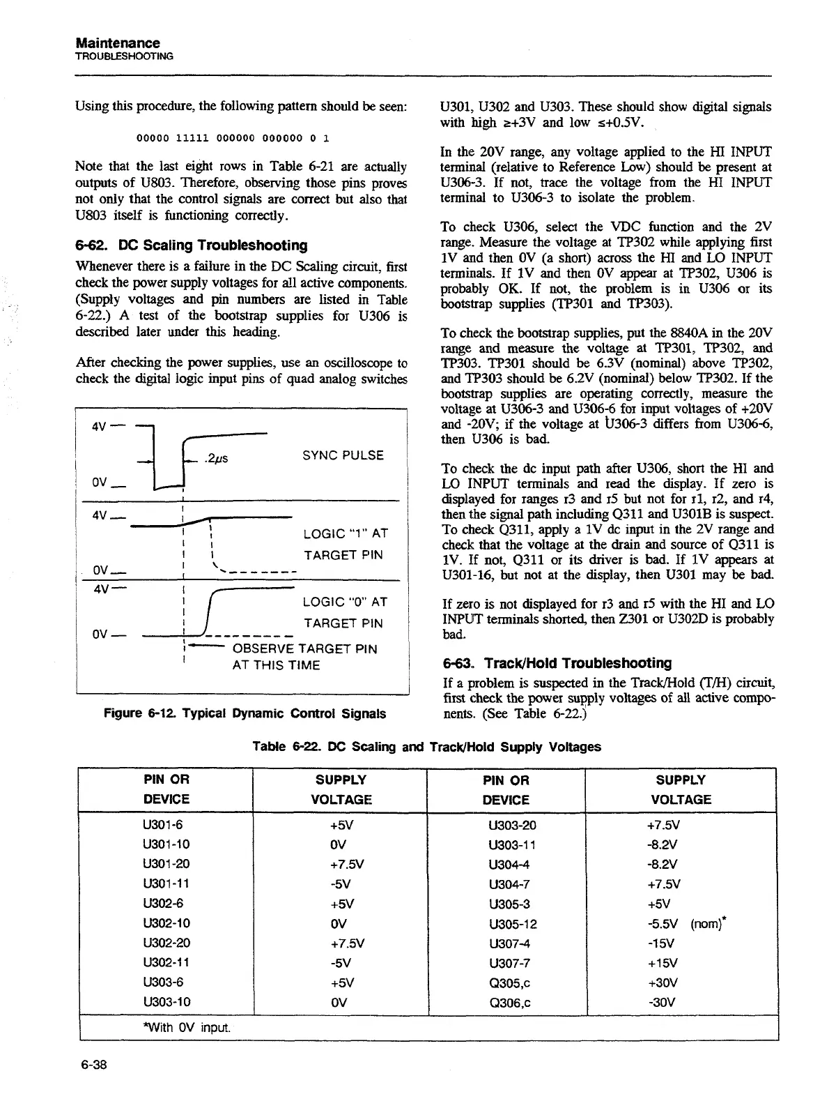
After checking the power supplies, use an oxilloscope to
check the digital logic input pins of quad analog switches
4v-
ur
SYNC PULSE
ov
,
I
I
4v-
I
F!
LOGIC
"1"
AT
I
I
I
I
TARGET
PIN
ov
-
]
'
.-------
4v
-
I
r-'
LOGIC
"0"
AT
I!
-
-
-
-
-
-
-
-
TARGET PIN
ov
-
1-
OBSERVE TARGET PIN
I
AT THIS TIME
-
Figure
6-12
Typical Dynamic Control Signals
PIN OR
DEVICE
U301, U302 and U303. These should show digital signals
with
high
r+3V and low s+0.5V.
In
the
20V range, any voltage applied to the HI INPUT
terminal (relative to Reference
Low)
should
be
present at
U3N-3. If not, trace the voltage from the HI INPUT
terminal to
U306-3 to isolate the problem.
To check U306, select the VDC function and the 2V
range. Measure the voltage at TP302 while applying first
1V and then OV (a short) across the HI and
LO
INPUT
terminals. If 1V and then OV appear at TP302, U306 is
probably
OK.
If not, the problem is in U306 or
its
bootstrap supplies (TP301 and TP303).
To check the bootstrap supplies, put the
8840A
in the 20V
range and measure the voltage at TP301, TP302,
and
TP303. TP301 should be 6.3V (nominal) above TP302,
and TP303 should
be
6.2V (nominal) below TP302. If the
bootstrap supplies are operating correctly, measure the
voltage at
U306-3 and U306-6 for input voltages of i20V
and -20V; if the voltage at b306-3 differs from U306-6,
then U306 is bad.
To check the dc input path after
U306,
short the HI and
LO
INPUT terminals and read the display. If zero is
displayed for ranges r3 and r5 but not for 11, r2, and r4,
then the signal path including Q311 and U301B is suspect.
To check Q311, apply a 1V dc input in the 2V range and
check that the voltage at the drain and source of Q311 is
1V. If not, Q311 or
its
driver is bad. If 1V appears at
U301-16, but not at the display, then U301 may
be
bad.
If zero is not displayed for r3 and r5 with the HI and
LO
INPUT terminals shorted, then W01 or U302D is probably
bad.
6-63.,
TracWHold Troubleshooting
If a problem is suspected in the Trackmold
(T/H)
circuit,
first
check
the power supply voltages of all active compo-
nents. (See
able
6-22.);-
-
-
Table
6-22.
DC
Scaling and TracWHold Supply Voltages
With
OV
input.
SUPPLY
VOLTAGE
+7.5V
-8.2V
-8.2V
+7.5V
+5V
-5.5V
@om)*
-1
5V
+15V
+30V
-3OV
SUPPLY
VOLTAGE:
+5V
OV
+7.5V
-5V
+5V
OV
+7.5V
-5V
+5V
OV
PIN
OR
DEVICE
U303-20
U303-11
U304-4
U304-7
U305-3
U305-12
U307-4
U307-7
Q305,c
Q306.c
Artisan Technology Group - Quality Instrumentation ... Guaranteed | (888) 88-SOURCE | www.artisantg.com

 Loading...


