Maintenance
EXTERNAL TRIGGER POLARITY SELECTlON
(Option
-05
Only)
6-37.
Initial Troubleshooting Procedure
WARNING
TO AVOID INJURY OR EQUIPMENT
DAMAGE, USE DUCT REPLACEMENT
PARTS FOR
AU PROTECTION
COM-
PONENTS.
When a problem occurs in the
8&40A,
first verify the
problem is actually in the instrument. If the problem
occurs when the instrument is in a system, check to see if
the same problem exists when under local control. Watch
the display
as
the instrument is turned on to see if any of
the digital self-test error codes appear indicating a
digital
failure. If the malfunction does not involve the True RMS
AC or IEEE-488 options, remove the option(s) from the
instrument before proceeding.
6-35.
EXTERNAL TRIGGER POLARITY
SELECTION (Option
-05
Only)
The
EXT
TRIG input is factory-configured with negative
polarity (trigger on falling-edge). This polarity is set by
jumper
E902 on the IEEE-488 Interface PCA. To select
positive polarity (trigger on rising-edge), remove jumper
E902 and add jumper E903.
6-36.
TROUBLESHOOTING
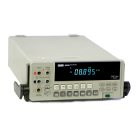
The 8840A is designed to
be
easily maintained and
repaired. Both the analog and digital circuits have built-in
diagnostic self-tests and troubleshooting modes to facili-
tate troubleshooting and repair. The instrument's circuits
allow troubleshooting and repair with basic electronic
troubleshooting equipment such
as
a multimeter and oscil-
loscope. The troubleshooting mode in the digital controller
circuitry generates special test signals to
allow trouble-
shooting and repair without a special test signal generator
or complex logic analyzer. Using the information in this
section, a technician should
be
able to troubleshoot and
repair the 8840A very efficiently.
If the display lights up, perform the self-test by pressing
the SRQ button for
3
seconds. (Remember, the input
terminals must be disconnected from the test leads during
the self-tests. Otherwise, the
8840A may indicate errors
are present.) The test numbers will appear consecutively.
"ERROR will appear on the display if a test should fail.
The 8840A
can
be
held in each of the test configurations
by momentarily pressing the SRQ button. (Press any but-
ton to continue the tests.) With the description of the
self-tests given below, it may be possible to isolate the
failure. For reference, the states of various switches and
logic lines are shown in Table
6-16
for each function,
range, and reading rate.
If
only one or a few failures appear in the self-tests, the
problem is usually in the
DC
Scaling circuit. By wefully
analyzing which failure(s) occurred, the fault can be
located to within a few components. (Table
6-17
shows
which components are exercised by each of the analog
tests.) The heading
DC
Scaling Troubleshooting provides
detailed instructions on locating and repairing DC Scaling
ciircuit problems. However, before troubleshooting the
DC
Scaling circuit, all of the power supply levels should
be
measured to verify they are within the limits specified in
Table
6-23
under Power Supply Troubleshooting, later in
this section.
Some failures will cause many
self-tests to fail. If this
occurs,
the fault is usually in the Track/Hold circuit, the
AID
Converter, the Digital Controller circuit, or the Power
Supply.
Again,
measure all of the power supply levels
according to the limits specified in Table 6-23. The next
step is to isolate the problem to a specific section.
If the self-tests display a large number of errors or if
readings are noisy
andlor in error, the problem is usually
in. the
A/D
Converter or TracWold circuit.
(A
large
iulmber of errors can also be caused by a problem in the
Ohms Current Source.)
To
isolate the problem, connect a
ju.mper between PI03 and Reference Low (TP306, or the
L-shaped shield around U202). The display should typi-
cally read less than approximately
35
counts (i.e.,
dMl0XX
where
XX
is less than 35) on the 2V dc range. If
a good reading
can
be
obtained (less than approximately
35 counts), the
AID
Converter and Precision Voltage
Reference circuits are most likely good.
A
more conclu-
sive test
can
be
made by connecting a low-impedance dc
source between Reference Low and TP103 with
an
output
voltage between -2.OV and +2.OV. The reading on the
display will
be
of opposite polarity to the voltage applied
to TF'103. (Disconnecting one end of R318 will usually
make it possible to display readings within 0.1% to 0.5%
of the actual input.) After it has been determined that the
AD
Converter or the TracWHold circuit is not functioning
properly, proceed to the corresponding heading for
detailed troubleshooting instructions and guidelines.
A failure in the instrument may cause the 8840A to
display random patterns or nothing at all. Usually, analog
circuit failures do not cause the display to go blank or
display random patterns. The best place to start
tlrouble-
shooting a "dead" instrument or an instrument with a
non-functional display is to check the power supply with a
voltmeter for proper levels and to use an oscilloscope to
check the supplies for oscillations. If all of the supplies are
working correctly, check the clock for the In-Guard
PC
at
U202-2. The signal should be an 8 MHz sine wave
approximately
3.5V peak-to-peak. Then check the
1
MHz
output of the
AID
IC
(U101) at U212-3. (If not present,
check at the
AD
IC at U101-14.) The signal should be a
1
MHz
square wave approximately
5V
peak-to-peak. The
8
MHz
sine wave is generated by the clock circuit of the
In-Guard
K,
and the I
MHz
signal is the
8
MHz
signal
divided by a counter in the
A/D
IC. If the clock signals are
correct, proceed to the heading Digital Controller Trouble-
shooting, below, for detailed troubleshooting instructions.
Artisan Technology Group - Quality Instrumentation ... Guaranteed | (888) 88-SOURCE | www.artisantg.com

 Loading...