Maintenance
TROUBLESHOOTING
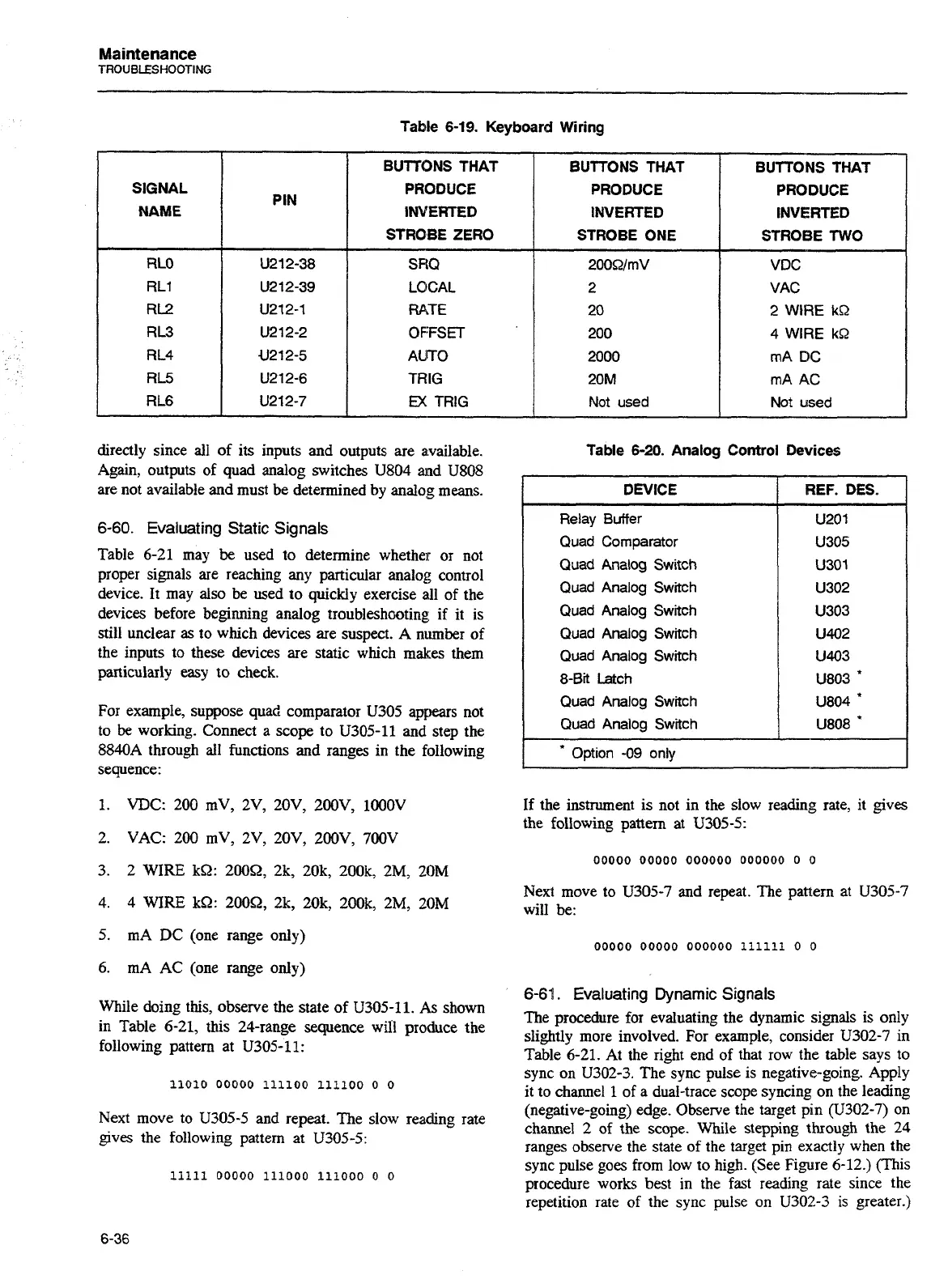
Table
6-19.
Keyboard Wiring
directly since all of its inputs and outputs are available.
Again, outputs of quad analog switches U804 and U808
are not available and must be determined by analog means.
SIGNAL
NAME
RLO
RL1
RL2
RL3
RL4
RL5
RL6
6-60. Evaluating Static Signals
Table 6-21 may
be
used to determine whether or not
proper signals are reaching any particular analog control
device. It may also be used to quickly exercise all of the
devices before beginning analog troubleshooting
if
it is
still unclear
as
to which devices are suspect. A number of
the inputs to these devices are static which makes them
particularly easy to check.
For example, suppose quad comparator
U305 appears not
to
be
working. Connect
a
scope to U305-11 and step the
8840A through all functions
and
ranges in the following
sequence:
PIN
U212-38
U2 12-39
U212-1
U212-2
U212-5
U212-6
U212-7
1.
VDC: 200 mV, 2V, 20V, 200V, lOOOV
2. VAC: 200 mV, 2V, 20V, 200V, 700V
BUTTONS THAT
PRODUCE
INVERTED
STROBE ZERO
SRQ
LOCAL
RATE
0
FFS
ET
AUTO
TRIG
EX
TRIG
3. 2 WIRE kS2: 20052, 2k, 20k, 200k, 2M,
20M
4.
4
WIRE kS2: 20052, 2k, 20k, 200k, 2M,
20M
BUTTONS THAT
PRODUCE
INVERTED
STROBE ONE
200SZ/mV
2
20
200
2000
20M
Not used
5. mA DC (one range only)
BUTTONS THAT
PRODUCE
INVERTED
STROBE
TWO
VDC
VAC
2
WIRE
kQ
4 WIRE
kQ
mA
DC
mA
AC
Not used
6.
mA AC (one range only)
While doing this, observe the state of U305-11. As shown
in Table 6-21, this 24-range sequence wiil produce the
following pattern at
U305-11:
Next move to U305-5 and repeat. The slow reading rate
gives the following pattern at U305-5:
Table
6-20.
Analog Control Devices
I
*
Option
-09
only
DEVICE
Relay Buifer
Quad Comparator
Quad Analog
Switch
Quad Analog
Switch
Quad Analog
Switch
Quad Analog
Switch
Quad Analog
Switch
8-Bit
Latch
Quad Analog
Switch
Quad Analog
Switch
If the instrument is not in the slow reading rate, it gives
the
following pattern at U305-5:
REF.
DES.
U201
U305
U301
U302
U303
U402
U403
U803
*
U804
'
U808
*
Next move to U305-7 and repeat. The pattern at U305-7
will be:
6-61. Evaluating Dynamic Signals
The procedure for evaluating the dynamic signals is only
slightly more involved. For example, consider U302-7 in
Table 6-21. At the right end of that row the table says to
sync on
U302-3. The sync pulse is negative-going. Apply
it
to channel
1
of a dual-trace scope syncing on the leading
(negative-going) edge. Observe the target pin (U302-7) on
channel 2 of the scope. While stepping through the
24
ranges observe the state of the target pin exactly when the
sync pulse goes from low to high. (See Figure 6-12.) (This
procedure works best in the fast reading rate since the
repetition rate of the sync pulse on
U302-3 is greater.)
Artisan Technology Group - Quality Instrumentation ... Guaranteed | (888) 88-SOURCE | www.artisantg.com

 Loading...


