Maintenance
TROUBLESHOOTING
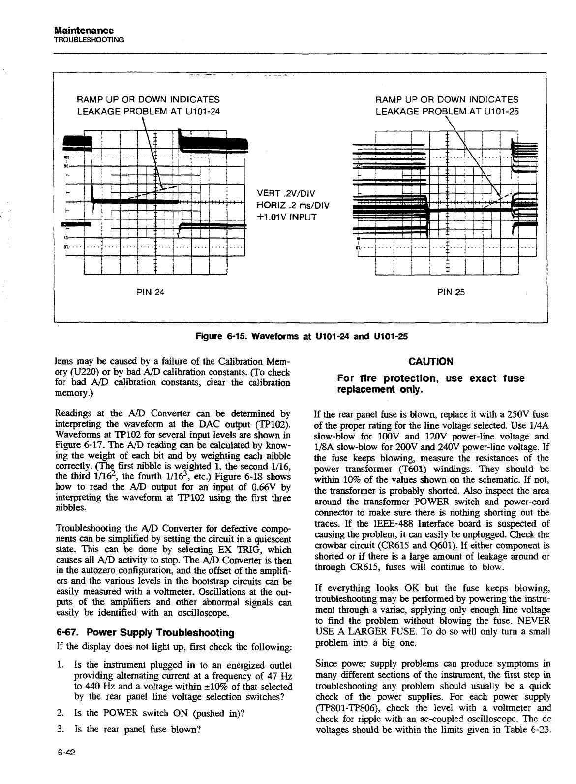
RAMP
UP
OR
DOWN INDICATES
LEAKAGE PROBLEM AT
U101-24
i,,.....
................
1
1
PIN
24
VERT .2V/DIV
HORIZ
.2
rns/DIV
+1.01V
INPUT
RAMP
UP
OR
DOWN
INDICATES
LEAKAGE
PROBLEM
AT
U101-25
\
PIN
25
Figure
6-15.
Waveforms
at
U101-24
and
U101-25
lems may
be
caused by a failure of the Ca1ibratio:n Mem-
ory (U220) or by bad
A/D
calibration constants. (To check
for bad
AID
calibration constants, clear the calibration
memory
.)
Readings at the
AD
Converter can
be
determined by
interpreting the waveform at the DAC output (T'P102).
Waveforms at TP102 for several input levels are slhown
in
Figure 6-17. The
AJD
reading
can
be calculated by know-
ing the weight of each bit and by weighting each nibble
correctly. (The first nibble is weighted
1,
the second 1/16,
the third 1116~~ the fourth l/16~, etc.) Figure 6-18 shows
how to read the
A/D
output for
an
input of O.&V by
interpreting the waveform at TP102 using the first three
nibbles.
Troubleshooting the
A/D
Converter for defective compo-
nents
can
be
simplified by setting the circuit in a quiescent
state. This
can
be done by selecting
EX
TRIG, which
causes all
AID
activity to stop. The
AD
Converter is then
in the autozero configuration, and the offset of the arnplifi-
ers and the various levels in the bootstrap circuits
can
be
easily measured with a voltmeter. Oscillations at ,the out-
puts of the amplifiers and other abnormal signals
can
easily be identified with an oscilloscope.
6-67.
Power Supply Troubleshooting
If the display does not light up, first check the foilowing:
1.
Is the instrument plugged in to
an
energized outlet
providing alternating current at a frequency
of
47
Hz
to 440
Hz
and a voltage within 210% of that selected
by the rear panel line voltage selection switches?
2.
Is the
POWER
switch
ON
(pushed in)?
3.
Is the rear panel fuse blown?
CAUTION
For fire protection, use exact fuse
replacement only.
If the rear panel fuse is blown, replace it with a 250V fuse
of the proper rating for the line voltage selected. Use
114A
slow-blow for lOOV and 120V power-line voltage and
1/8A slow-blow for
200V
and 240V power-line voltage. If
the fuse keeps blowing, measure the resistances of the
power transformer (T601) windings. They should
be
within 10% of the values shown on the schematic. If not,
the transformer is probably shorted. Also inspect the area
around the transformer POWER switch and power-cord
connector to make sure there is nothing shorting out the
traces. If the IEEE-488 Interface board is suspected of
causing the problem, it can easily
be
unplugged. Check: the
crowbar circuit (CR615 and Q601). If either component is
shorted or if there is a large amount of leakage around or
through
CR615, fuses will continue to blow.
If everything looks
OK but the fuse keeps blowing,
troubleshooting may
be
performed by powering the instru-
ment through a variac, applying only enough line voltage
to find the problem without blowing the fuse.
NEVER
USE
A
LARGER FUSE. To do so will only turn a simall
problem into a big one.
Since power supply problems can produce symptoms in
many different sections of the inst~ment, the first step in
troubleshooting any problem should usually be
a
quick
check of the power supplies. For each power supply
(TP801-TP806), check the level with a voltmeter and
check for ripple with an ac-coupled oscilloscope.
The
dc
voltages should be within the limits given in Table
6-23.
Artisan Technology Group - Quality Instrumentation ... Guaranteed | (888) 88-SOURCE | www.artisantg.com

 Loading...


