Maintenance
CAUBRATlON
each function. To save time, the 8840A uses each input for
as
many ranges as possible.
A
function is calibrated by pressing the corresponding
function button. Once a function is selected, the
8840A
automatically steps through each range of that function,
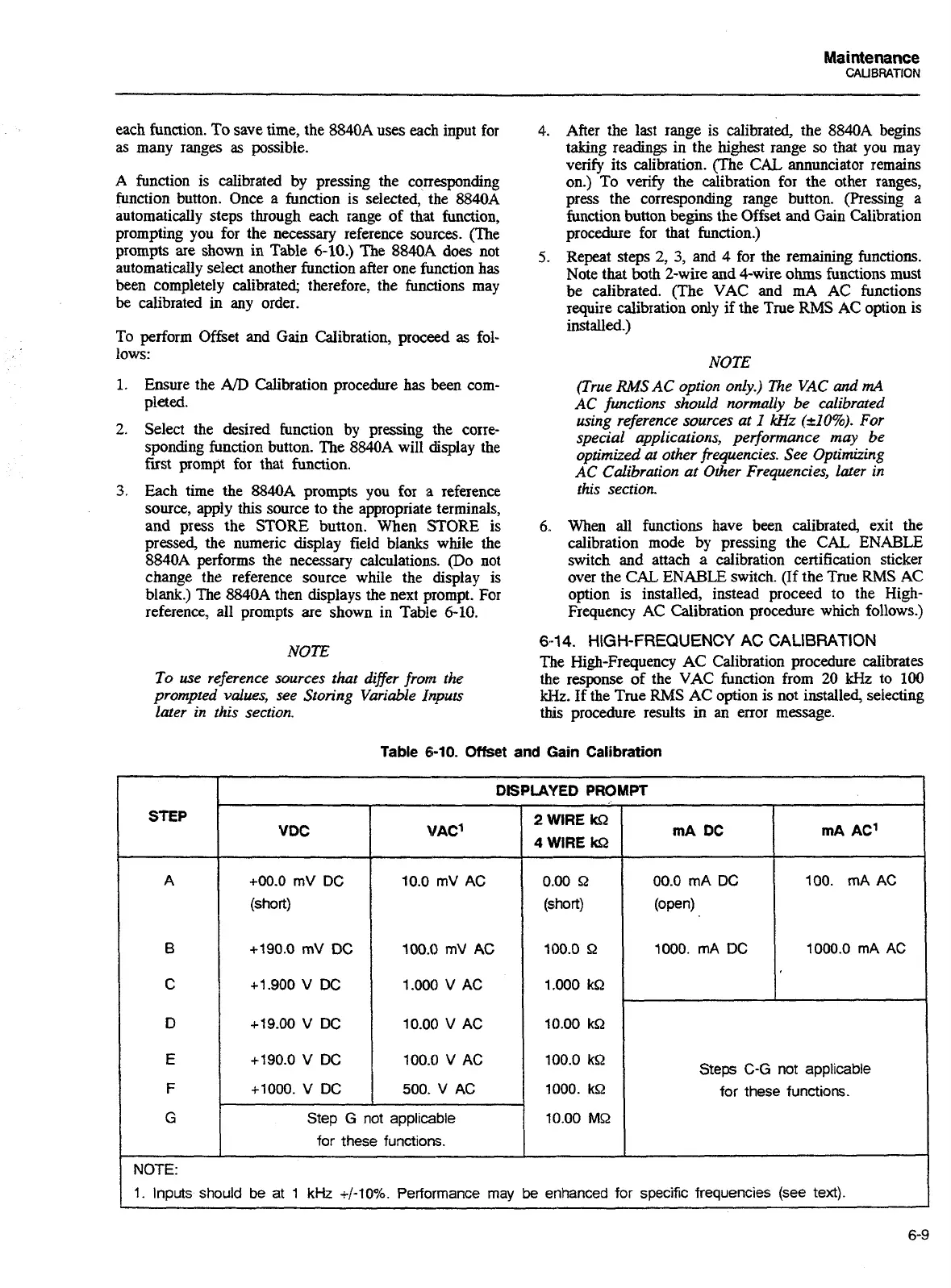
prompting you for the necessary reference sources. (The
prompts are shown in Table
6-10.)
The
8840A
does not
automatically select another function after one function has
been completely calibrated, therefore, the functions may
be calibrated in any order.
To perform Offset and Gain Calibration, proceed
as
fol-
lows:
1.
Ensure the
AD
Calibration procedure has been com-
pleted.
2.
Select the desired function by pressing the corre-
sponding function button. The 8840A will display the
fust prompt for that function.
3.
Each time the
8840A
prompts you for
a
reference
source, apply this source to the appropriate terminals,
and press the STORE button. When STORE is
pressed, the numeric display field blanks while the
8840A performs the necessary calculations. (Do not
change the reference source while the display is
blank.) The
8840A
then displays the next prompt. For
reference, all prompts are shown in Table
6-10.
NOTE
To
use
reference sources that dfler from the
prompted values, see Storing Variable Inputs
later in this section.
4..
After the last range is calibrated, the 8840A begins
taking readings in the highest range so that you may
verify its calibration. (The
CAL
annunciator remains
on.) To verify the calibration for the other ranges,
press the corresponding range button. (Pressing a
function button begins the Offset and Gain Calibration
procedure for that function.)
5.
Repeat steps
2,
3,
and
4
for the remaining functions.
Note that
both
2-wire
and
4-wire ohms functions must
be calibrated. (The VAC and mA AC functions
require calibration only
if
the True
RMS
AC
option is
installed.)
NOTE
(True
RMS
AC option only.) The VAC
and
mA
AC
fwrctions should normally
be
calibrated
using reference sources at
I
Wlz
(210%).
For
special applications, performance may be
optimized at other frequencies. See Optimizing
AC
Calibration
at
Other Frequencies, later in
this section.
6..
When
all
functions have been calibrated, exit the
calibration mode by pressing the CAL
ENABLE
switch and attach a calibration certification sticker
over the
CAL
ENABLE
switch.
(If
the True RMS AC
option is installed, instead proceed to the High-
Frequency AC Calibration procedure which follows.)
6-1
4.
HIGH-FREQUENCY
AC
CALIBRATION
The High-Frequency AC Calibration procedure calibrates
the response of the VAC function from 20
kHz
to
100
Hz.
If the True RMS AC option is not installed, selecting
this procedure results in
an
error message.
Table
6-10.
Offset
and Gain Calibration
DISPLAYED
PROMPT
2
WlRE
162
VDC
I
vAcl
I
4
WlRE
162
+00.0
mV
DC
(short)
+190.0
mV
DC
+I
900
V
DC
+19.00
V
DC
+190.0
V
DC
+1000.
V
DC
0.00 R
(short)
100.0
9
1.000 kQ
10.00 kQ
1
100.0
kR
Step
G
not
applicable
for these functions.
Steps
C-G
not applicable
for these functions.
STEP
A
6
C
D
E
F
G
10.00
MQ
-
-
NOTE:
1.
ItIp~ts should be at
1
kHz
+/-lo%.
Performance
may
be
enhanced for specific frequencies (see
text).
I
Artisan Technology Group - Quality Instrumentation ... Guaranteed | (888) 88-SOURCE | www.artisantg.com

 Loading...


