Maintenance
TROUBLESHOOTING
3. Short
TP903
to TP905.
4.
Power up the 8840A. The 8840A should display
ERROR 50. To exit the troubleshooting mode, open
the jumper and cycle the POWER switch from off to
on.
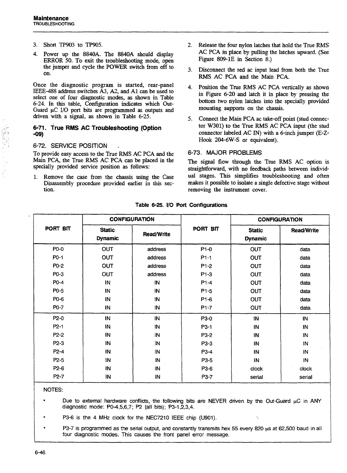
Once the diagnostic program is started, rear-panel
IEEE-488
address switches
A3,
A2,
and A1
can
be used to
select one of four diagnostic modes,
as
shown in Table
6-24. In this table, Configuration indicates which Out-
Guard
pC
110
port bits are programmed
as
outputs and
driven with
a
signal, as shown in Table 6-25.
6-71.
rue
RMS
AC
Troubleshooting (Option
-09)
6-72.
SERVICE POSITION
-
To provide easy access to the True RMS AC PCA and the
Main PCA, the True
RMS
AC PCA
can
be
placed in the
specially provided service position as follows:
1.
Remove the case from the chassis using the Case
Disassembly procedure provided earlier in this sec-
tion.
2.
Release the four nylon latches that hold the True RMS
AC PCA in place by pulling the latches upward. (See
Figure 809-1E in Section 8.)
3.
Disconnect the red ac input lead from both the Rue
RMS AC PCA and the Main PCA.
4.
Position the True RMS AC PCA vertically
as
shown
in Figure 6-20 and latch it in place
by
pressing the
bottom two nylon latches into the specially provided
mounting supports on the chassis.
5.
Connect the Main PCA ac take-off point (stud connec-
tor W301) to the True RMS AC PCA input (the stud
connector labeled AC
IN)
with a dinch jumper
(E-Z-
Hook
204-6W-S
or equivalent).
6-73.
MAJOR PROBLEMS
The signal flow through the True RMS AC option
is
straightforward, with no feedback paths between individ-
ual stages. This simplifies troubleshooting and often
makes it possible to isolate
a
single defective stage without
removing the instrument cover.
Table
6-25.
VO
Port Configurations
Static
Readwrite
Dynamic
OUT
OUT
OUT
OUT
IN
IN
address
address
address
address
IN
IN
OUT
OUT
OUT
OUT
I
OUT
I
OUT
OUT
IN
IN
I
IN
I
PI-7
I
OUT
IN
-
--
IN
IN
IN
IN
IN
IN
clock
serial
data
data
data
data
data
data
data
data
IN
IN
clock
serial
NOTES:
Due to
external hardware conflicts, the following bits
are
NEVER driven by the Out-Guard
pC
in
ANY
diagnostic mode:
P04,5,6,7;
P2
(all
bits);
P3-1,2,3,4.
P3-6
is
the
4
MHz
clock for the
NEC7210
IEEE chip
(U901).
\
P3-7
is
programmed
as
the
serial output, and constantly transmits hex
55
every 820
ps
at 62,500 baud in all
four diagnostic
modes.
This causes
the
front panel error message.
Artisan Technology Group - Quality Instrumentation ... Guaranteed | (888) 88-SOURCE | www.artisantg.com

 Loading...


