Remote
Pyading
DEVICE-DEPENDENT
MMA
D
SET
I
I
-
-
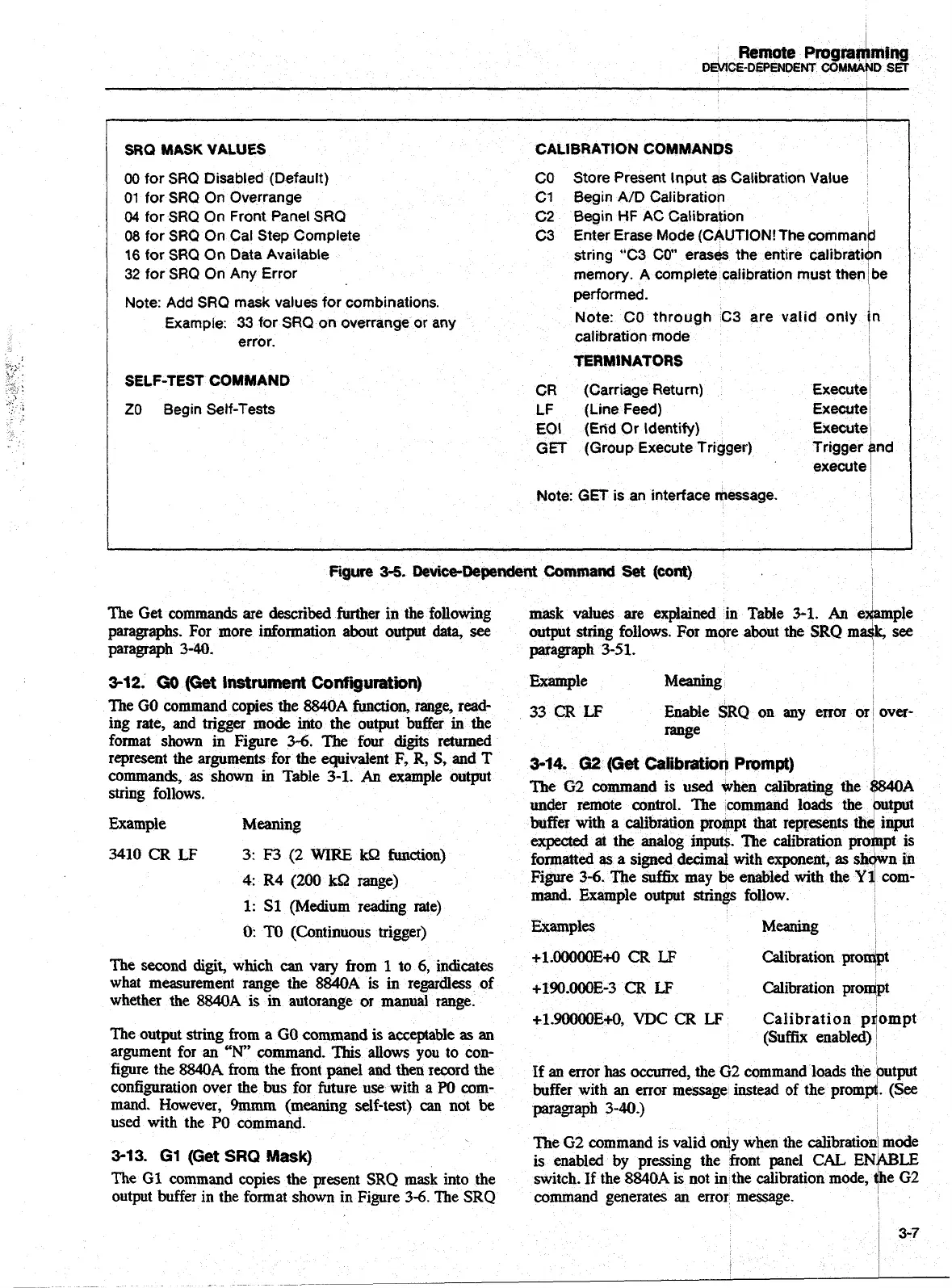
SRQ
MASK
VALUES CALlBRATtON COMMANDS
I
00
for SRQ Disabled (Default) CO
Store Present Input
as
Calibration Value
01 for SRQ On Overrange
C1
Begin A/D Calibration
04
for
SRQ
On Front Panel SRQ C2 Begin
HF
AC Calibration
I
08 for SRQ On Cal Step Complete
C3
Enter Erase Mode (CAUTION! The comman/d
16
for SRQ On Data Available
string "C3 CO" erases the entire calibratiOn
32 for SRQ On Any Error
memory.
A
complete calibration must then
be
Note:
Add
SRQ mask values for combinations.
Example:
33
for SRQ on overrange or any
error.
SELF-TEST
COMMAND
ZO Begin Self-Tests
performed.
Note: CO through C3 are valid only
/n
calibration mode
TERMlNATORS
1
CR (Carriage Return)
Execute
l
LF (Line Feed) Execute
~
EOI
(Etid
Or Identify) Execute
1
GET
(Group Execute Trigger)
Trigger
Bnd
execute
Note: GET
is
an interface message.
I
I
Figure
3-5.
Device-Dependent
Command
Set
(cont)
The
Get
commands are
described
further in the following
mask
values are explained
in
Table
3-1.
An
ehple
paragraphs. For more information about output
data,
see
output string follows. For more about the
SRQ
mdk, see
paragraph
340.
paragraph 3-51.
3-12.
GO
(Get
Instrument
Configuration)
Example Meaning
The
GO
command copies the
8840A
function,
range,
read-
33
CR
LF
Enable
SRQ
on any error
or
over-
ing rate, and trigger
mode
into the output buffer
in
the
format
shown
in Figure 3-6. The four
digits
returned
rwe
represent the arguments for the equivalent F,
R,
S,
and T
3.14.
02
(~a
Calibraf~)n
Pmmpt)
commands, as shown
in
Table
3-1.
An
example output
string follows.
The
G2
command is
used
when
calibrating
the
~/?~MOA
under remote control. The
command
loads the putput
Example
Meaning
buffer
with
a calibration prompt that represents
th
input
expected
at the analog inputs. 'The calibration
pro
pt
is
3410
CR
LF
3:
F3
(2
WIRE
kS2
function)
formatted
as
a signed
decimal
with exponent,
as
sh
in
4:
R4
(200
kQ
range)
mand. Example output strings follow.
k
Figure
3-6.
The
suffix
may
be
enabled with
the
Yd
com-
1:
S1
(Medium
reading rate)
0:
TO
(Continuous trigger)
Examples Meaning
The second
digit,
which
can
vary from
1
to
6,
indicates
+1.00000E+0
CR
LF
Calibration pro&
what measurement range the
8840A
is in regardless of
+190.-~00~-3
CR
LF
Calibration pro4pt
whether
the
8840A
is
in autorange or manual range.
+1.90000E+O,VDCCRLF Calibrationpqompt
The output
string
from
a
GO
command is acceptable
as
an
(Suffix
enabled)
argument for an
"N
command.
This
allows you to con-
figure the
8840A
from the front panel
and
then
record the
If
an
error
has
occurred,
the 02 command loads the output
configuration over the bus for future use with a
PO
com-
buffer with an error message instead of the
promfl.
(See
mand. However, 9mmm
(meaning
self-test)
can
not
be
paragraph 3-40.)
used with the
PO
command.
The
G2
command is valid only when the calibration mode
3-13.
G1
(Get
SRQ
Mask)
is enabled
by
pressing the front panel
CAL
ENWLE
The
GI
command copies the present
SRQ
mask
into the
switch. If the
8840A
is
not in the calibration mode,
4)e
G2
output
buffer
in the format shown in Figure 3-6. The SRQ command generates
an
error message.
Artisan Technology Group - Quality Instrumentation ... Guaranteed | (888) 88-SOURCE | www.artisantg.com

 Loading...


