CONTROLS, INSTRUMENTS AND'·OPERATION-·
--
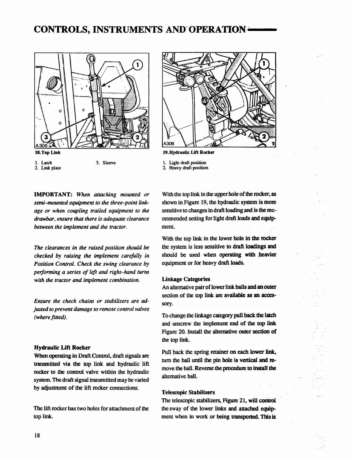
18.
Top Link
L Latch
2.
Link plate
3.
Sleeve
IMPORTANT:
When attaching mounted or
semi-mounted equipment to the three-point link-
age or when coupling trailed equipment to the
drawbar, ensure that there is adequate clearance
between the implement
and
the tractor.
The clearances in the raised position should be
checked
by
raising the implement carefully in
Position Control.
Check the swing clearance by
performing a series
of
left and right-hand turns
with the tractor
and
implement combination.
Ensure the check chains or stabilizers are
ad-
justed w prevent damage to remote control valves
(where fitted).
Hydraulic
Lift
Rocker
When
operating in Draft Control, draft
signals
are
transmitted via the top link
and
hydraulic lift
rocker
to
the control valve within
the
hydraulic
system.
The
draft signal transmitted
may
be
varied
by
adjustment
of
the lift rocker
coruiections.
The
lift rocker has
two
holes
for attachment of
the
top
link.
18
19.
Hydraulic Lift Rocker
1.
Light draft position
2.
Heavy draft position
With
the
top
link
in
the
upper hole
of
the rocker,
as
shown
in
Figure
19,
the hydraulic system is more
sensitive
to
changes
in draft loading and
is
the
rec-
ommended
setting for light draft loads
and
equip-
ment.
With
the
top
link in
the
lower hole
in
the rocker
the
system
is
less sensitive
to
draft loadings
and
should
be
used
when
operating with .
.tieavier
equipment
or for
heavy
draft
loads.
Linkage Categories
An alternative pair oflower link balls
and
an outer
section
of the top link
are
available as
an
acces-
sory.
To
change
the
linkage
category
pull back
the
latch
and
wiscrew
the
implement
end
of
the top
link
Figure
20.
Install
the
alternative outer section
of
the
top
link.
Pull
back
the
spring retainer on each lower link,
tum
the
ball
until the pin hole is venical
and
re-
move
the
ball.
Reverse
the
procedure to install
the
altemati
ve
ball.
Telescopic Stabilizers
The
telescopic
stabilizers, Figure
21,
will conttol
the
sway
of
the
lower links
and
attached equip-
ment
when
in
work or
being
transported.
111is
is
 Loading...


