CONTROLS, INSTRUMENTS
AND
OPERATION·--
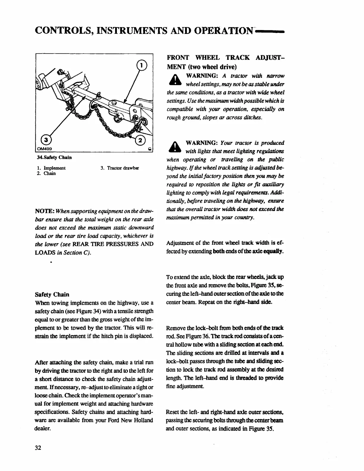
OM499
34.Safety Chain
1. hnplement 3. Tractor drawbar
2.
Chain
NOTE:
When
supporting
equipment
on
the
draw-
bar
ensure
that the total weight
on
the
rear
axle
does
not exceed
the
maximum
static
downward
load or
the
rear tire
load
capacity,
whichever
is
the lower (see REAR TIRE PRESSURES
AND
LOADS
in
Section
C).
Safety
Chain
When towing implements
on
the highway,
use
a
safety chain (see Figure 34) with a tensile strength
equal to
or
greater than the gross weight
of
the
im-
plement
to
be
towed by
the
tractor. This will
re-
strain
the
implement
if
the hitch pin is displaced.
After
attaching the safety chain, make a trial run
by driving the tractor to the right and to the left for
a short distance
to
check the safety chain adjust-
ment.
ff
necessary, re-adjust
to
eliminate a tight or
loose chain. Check the implement operator's man-
ual for implement weight
and
attaching
hardware
specifications. Safety chains and attaching hard-
ware are available from your Ford New
Holland
dealer.
32
FRONT WHEEL TRACK ADJUST-
MENT
(two wheel drive)
A
WARNING:
A tractor
with
Mn'OW
4lla wheel
settings,
may
not
be
as
stable
under
the
same
conditions,
as
a tractor
with
wide
wheel
settings.
Use
the
maximum
width possible
which
is
compatible
with
your operation, especially
on
rough
ground,
slopes
ar across
ditches.
A
WARNING:
Your
tractor
is produced
4lla
with
lights
that meet lighting
regulations
when
operating
or traveling
on
the
public
highway.
If
the
wheel
track setting
is
adjusted
be-
yond
the
initial factory position
then
you
may
be
required
to
reposition
the
lights
or fit auxiliary
lighting
to
comply
with
legal
requirements.
Addi-
tionally,
before
traveling
on
the
highway,
ensure
that
the
overall
tractor
width
does
not exceed the
maximum
permitted
in
your
country.
Adjustment
of
the front wheel track width is ef-
fected
by extending both ends
of
the axle equally.
To extend the axle, block the rear wheels, jack up
the front axle
and
remove the bolts, Figure 3S,
se-
curing
the left-hand outer section
of
the axle to the
center beam. Repeat on the right-band side.
Remove
the lock-bolt from both ends
of
the
track
rod.
See
Figure
36.
The
track rod consists
of
a cen-
tral
hollow tube with a sliding section at each
end.
The
sliding sections
are
drilled at intervals and a
lock-bolt
passes
through
the
tube
and
sliding sec-
tion
to
lock the track rod assembly
at
the
desired
length. The left-hand
end
is
threaded
to
provide
fine adjustment.
Reset the left- and right-hand
axle outer sections,
passing
the
securing
bolts through the center beam
and
outer sections, as indicated in Figure 35.
 Loading...


