--------------SECTION
A
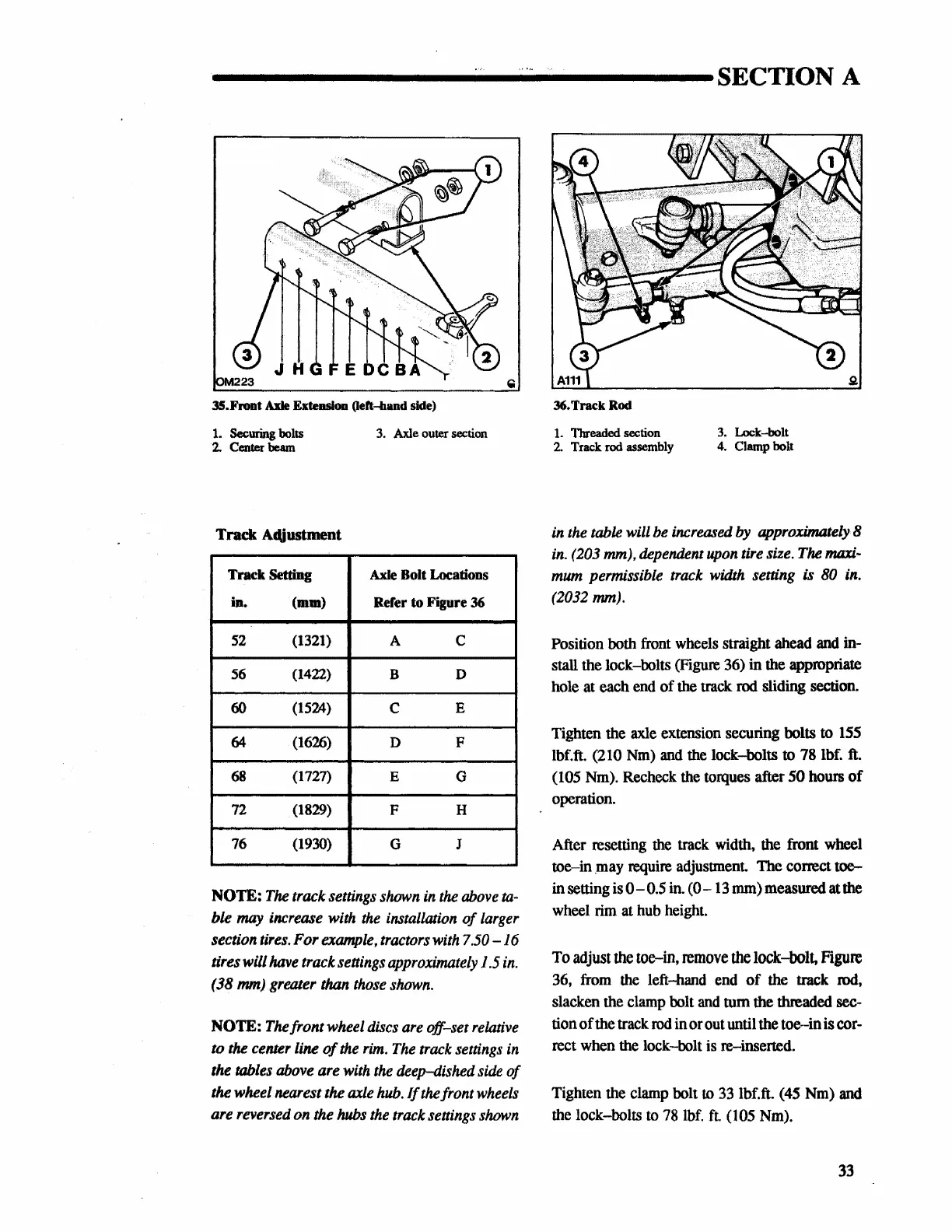
35.Front
Axle Extension (left-band side)
1. Securing bolts
3.
Axle
outer section
2. Center beam
Track Adjustment
Track Setting
Axle
Bolt Locations
in.
(mm)
Refer
to
Figure 36
52
(1321)
A
c
56
(1422)
B
D
60
(1524)
c
E
64
(1626)
D
F
68
(1727)
E
G
72
(1829)
F H
76
(1930)
G J
NOTE:
The
track settings
shown
in
the
above
ta-
ble
may
increase with
the
installation
of
larger
section
tires.
For
example,
tractors
with
7.50-16
tires will
have
track
settings
approximately
1.5
in.
( 38 mm)
.greater
than
those
shown.
NOTE:
The
front wheel
discs
are
off-set
relative
to
the
center line
of
the
rim.
The
track
settings
in
the
tables
above
are
with
the
deep-dished
side
of
the wheel nearest the
axle
hub.
If
thefrontwheels
are reversed on the
hubs
the
track settings
shown
36.
Track
Rod
1.
Threaded section
3.
Lock-bolt
2.
Track rod
assembly
4.
Clamp bolt
in
the
table will
be
increased
by
approximately 8
in.
(203
mm), dependent
upon
tire size.
The
maxi-
mum
permissible
track
width
setting is 80
in.
(2032 mm).
Position both front wheels straight ahead and in-
stall the lock-bolts (Figure 36)
in
the appropriate
hole at each end
of
the track rod sliding section.
Tighten the axle extension securing bolts
to
155
!bf.ft.
(210 Nm) and the lock-bolts to 78 lbf. ft.
(105 Nm). Recheck the torques after
50
hours
of
operation.
After resetting the track width, the front wheel
toe-in
.may require adjustment.
The
correct
toe-
in
sening is
0-0.5
in.
(0-13
mm) measured at the
wheel rim at hub height.
To
adjust
the
toe-in,
remove
the
lock-bolt,
Figure
36, from the left-hand end
of
the track rod,
slacken the clamp bolt and
tum
the
threaded
sec-
tion
of
the track rod
in
or
out until the
toe-in
is
cor-
rect when the lock-bolt is re-inserted.
Tighten the clamp bolt
to
33 lbf.ft. (45 Nm) and
the lock-bolts to 78 lbf.
ft.
(105 Nm).
33
 Loading...


