LUBRICATION
AND
MAINTENANCE
......
~,
__
..._....__
GENERAL MAINTENANCE (continued)
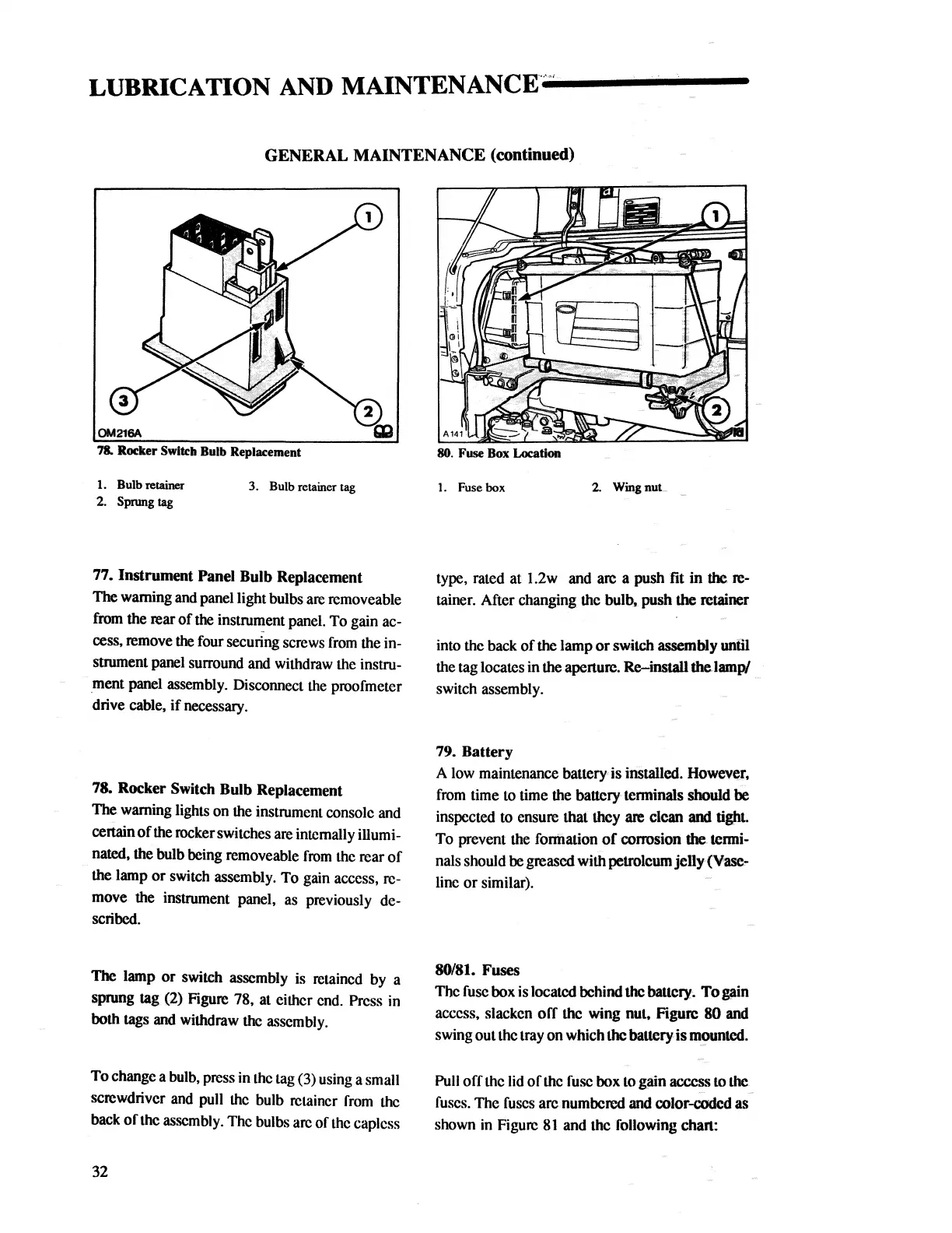
78. Rocker Switch Bulb Replacement
1. Bulb retainer
3. Bulb retainer tag
2.
Spnmg
tag
77. Instrument Panel Bulb Replacement
1be
warning
and
panel light bulbs
are
removeable
from
the rear
of
the instrument panel. To gain ac-
cess, remove
the
four securing screws
from
the in-
sbUment panel surround
and
withdraw the instru-
.ment
panel assembly. Disconnect
the
proofmeter
drive cable,
if
necessary.
78. Rocker Switch Bulb Replacement
1be
warning lights on the instrument console and
cenain
of
the
rockerswitches
are
internally illumi-
nated, the bulb being removeable
from
the rear
of
the lamp or switch assembly. To gain access, re-
move the instrument panel,
as
previously de-
scribed.
1be
lamp or switch assembly is retained
by
a
sprung tag
(2) Figure 78, at either end. Press in
both
tags and withdraw
the
assembly.
To change a
bulb,
press in the
tag
(3) using a small
screwdriver
and
pull
the
bulb retainer
from
the
back
of
the assembly. The bulbs
arc
of
the
caplcss
32
80. Fuse
Box
Location
1.
Fuse box
2.
Wingnut
..
type, rated at 1.2w and are a push fit in
the
re-
tainer. After changing the
bulb~
push
the
retainer
into the back
of
the
lamp
or
switch assembly uniil
the tag locates in
the aperture. Re-install
theJamp/
switch assembly.
79. Battery
A
low
maintenance battef)" is installed. Howevq,
from
time
to
time the battcf)" tenninals should
be
inspected
to
ensure that they
are
clean
and
tight.
To prevent the formation
of
a>rrosion
the
tenni-
nals should
be greased with petroleum jelly(Vase-
linc or similar).
80/81.
Fuses
The
fuse
box is located behind
the
battecy, To
pin
access, slacken
off
the wing nut, Figure 80 and
swing out the tray on which
the
battery is
m_!>untcd.
Pull
offlhc
lid
of
the
fuse
box
to
gain access
to
the.
fuses.
The
fuses
arc numbered and color-coded as
shown
in
Figure
81
and the following chan:
 Loading...


