---------------SECTION
A
20.Chanpag
the Linkage Category
1.
Top link end
3.
Ball
2.
Spring retainer
especially imponant when operating on slopes or
near fences, walls or ditches
and
with
certain
im-
plements. Check your Implement Operator's
Manual.
Each stabiliur consists
of
a fabricated,
square
section
tube
attac~ed
to a mounting bracket bolted
to
the outer ends
of
the rear
axle
housing. A
square-section rod, attached
to
the lower links,
is
a loose, sliding fit within the tube
and
the overall
length
of
the assembly
is
detennined
by
the
posi-
tion
ofa
pin that may be passed through drillings
in the
tube
and
rod.
The holes in
the
inner and outer sections
are
drilled
at
different centers
so
a
wide
range
of
stabi-
lizer settings
may
be achieved by selection
of
the
most suitable pair
of
holes.
In
practice,
the
implement should
be
attached
to
the
three-point
linkage with the locating pin
re-
moved
from
both stabilizers.
When
satisfactorily
aligned,
the
locating pins
should
be
passed
through any one
of
the
five holes
in
the
outer
sec-
tions that align
with
one
of
the
nine holes in
the
sliding inner section. With
1he
pins inserted in
this
manner, both stabilizers will
be
locked
as
a
rigid
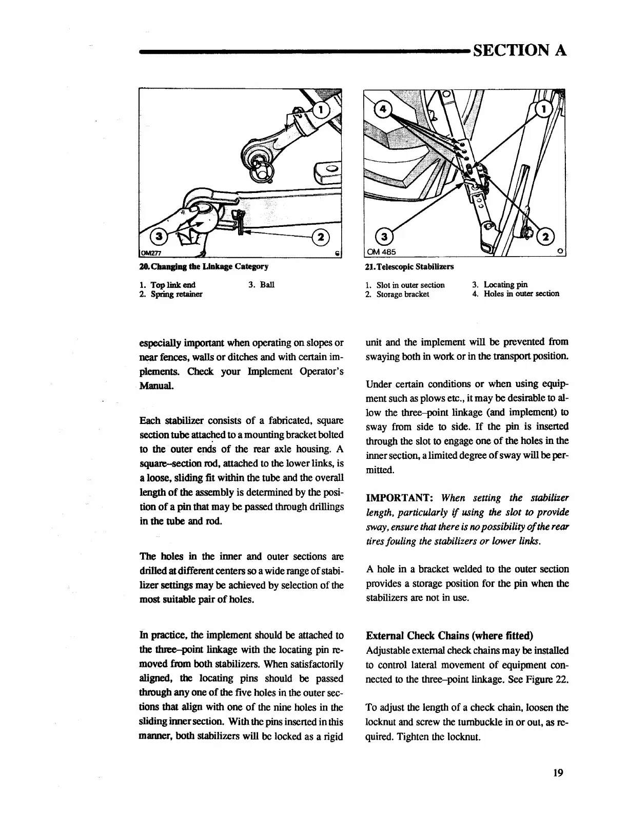
21. Telescopic Stabilizers
1.
Slot in outer section
3.
Locating
pin
2. Storage bracket
4.
Holes in outer section
unit
and
the implement will be prevented
from
swaying both in work or in the transport position.
Under certain conditions or when using equip-
ment
such
as
plows etc., it may be desirable
to
al-
low
the
three-point linkage (and implement) to
sway
from
side
to
side.
If
the pin is inserted
through
the
slot to engage one
of
the holes
in
the
inner section, a limited degree
of
sway will
be
per-
mitted.
IMPORTANT:
When
setting the stabilizer
length,
particularly if
using
the
slot
to
provide
sway,
ensure
that
there
is
no
possibility
of
the
rear
tires
fouling
the
stabilizers or lower
links.
A
hole
in a bracket
welded
to the outer section
provides a storage position for the pin
when
the
stabilizers
are
not
in
use.
External
Check
Chains
(where
titted)
Adjustable external check chains may
be
installed
to
control lateral movement
of
equipment con-
nected
to
the
three-point linkage.
See
Figure
22.
To
adjust
the
length of a check chain, loosen
the
locknut
and
screw
the
turnbuckle
in
or out,
as
re-
quired.
Tighten
the
locknut.
19
 Loading...


