------------------------------SECTION
A
To
reduce the rate
of
lift,
move
the
flow
control
valve knob clockwise.
Move
the knob counter-
clockwise
to
increase
the
rate
of
lift.
Draft Control Operation with Position Control
NOTE: When operating in Draft Control the Po-
sition Control lever should normally be at the bot-
tom
of
the quadrant. However, the Position Con-
trol lever
may
be
used in conjunction with Draft
4
Control to limit the maximum depth
to
achieve a
more even depth
of
cultivation in fields with
widely varying soil conditions.
Position Control may
be
used
together with
the
Draft Control
as
follows:
Set
the
Position Control lever at the maximum
de-
sired implement depth. The hydraulic system
will
not lower the implement below this depth. (This
will
also
prevent "diving" which may be encoun-
tered with light equipment, such
as
a rear blade,
when
grading or backfilling).
Adjust
the
Draft Control lever for the maximum
required draft load
{pull).
The hydraulic lift system will now provide nonnal
draft response within the
range
set
by
the
Position
Control. This adjustment provides a more
uni-
fonn depth while maintaining
an
even pull in
widely varying soil conditions.
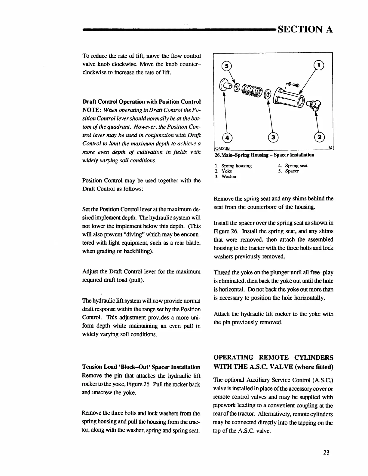
Tension Load
'Block-Out'
Spacer Installation
Remove
the pin that attaches the hydraulic lift
rocker
to
the yoke, Figure
26.
Pull the rocker back
and
unscrew the
yoke.
Remove the three bolts
and
lock washers
from
the
spring housing and pull
the
housing
from
the
trac-
tor,
along with the washer, spring
and
spring
seat.
OM238
26.
Main-Spring Housing - Spacer Installation
1.
Spring housing
4.
Spring seat
2.
Yoke
5.
Spacer
3. Washer
Remove
the spring seat and any shims behind the
seat
from
the counterbore
of
the housing.
Install the spacer over the spring seat
as
shown in
Figure
26.
Install the spring seat,
and
any
shims
that
were
removed, then attach the assembled
housing
to
the tractor with the three bolts and lock
washers previously removed.
Thread the yoke on the plunger until
all
free-play
is
eliminated, then back
the
yoke out until the hole
is
horizontal.
Do
not back the yoke out more than
is
necessary
to
position the hole horizontally.
Attach
the
hydraulic lift rocker to the yoke with
the pin previously removed.
OPERATING REMOTE CYLINDERS
WITH
THE
A.S.C. VAL VE (where fitted)
The optional Auxiliary Service Control (A.S.C.)
valve
is
installed in place
of
the accessory cover or
remote control valves and may
be
supplied with
pipework leading
to
a convenient coupling at the
rear of
the
tractor. Alternatively, remote cylinders
may
be
connected directly into the tapping on the
top
of the A.S.C. valve.
23
 Loading...


