5.2 Power supply unit
5-9
5.2 Power supply unit
5.2.1 General
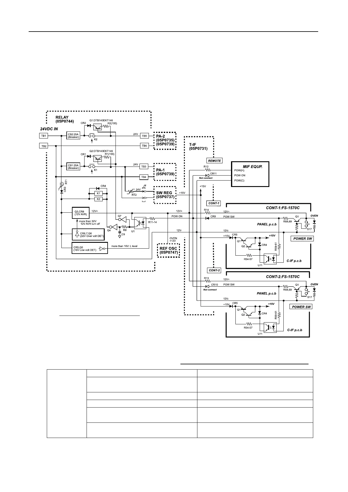
Fig.5.2.1 shows power supply lines in the system.
Table 5.2.1 summaries protectors provided on RELAY board.
Lowvoltage protector CR5 and Q6 which control U1.
Overvoltage protector
CR6, CR7 and Q6 which control +12 V
AVR consisting of Q3 and CR8.
PA1 over current protector 25 A breaker (CB1)
PA2 over current protector 25 A breaker (CB2)
SW REG board protector (05P0737)
Polyswitch (RT2), REU900
(Ih=9 A/It=18 A)
RELAY
board
(05P0744)
+12 V AVR protector
Polyswitch (RT1), REU135
(Ih=1.35 A/It=2.7 A)
Fig.5.2.1 Power supply lines
Table 5.2.1 Protectors in power supply circuit
When two FS-2570Cs are used, only the unit which is
connected to [CONT-1] port can turn on and off the system.
No.1 controller unit should be installed in W/H.
 Loading...