6.2 Self test of Antenna coupler
6-10
6.2 Self test of Antenna coupler
The antenna coupler provides self-test function as below.
To test the antenna coupler, AT-1560;
1. Remove the dummy board.
2. Set the DIP switch, S2-#2 to ON.
3. Set AUTO/MANUAL switch (S1) to “AUTO”. In “MANUAL” position, the self test
is not executed.
4. Set TUNE SW (S3) to ON.
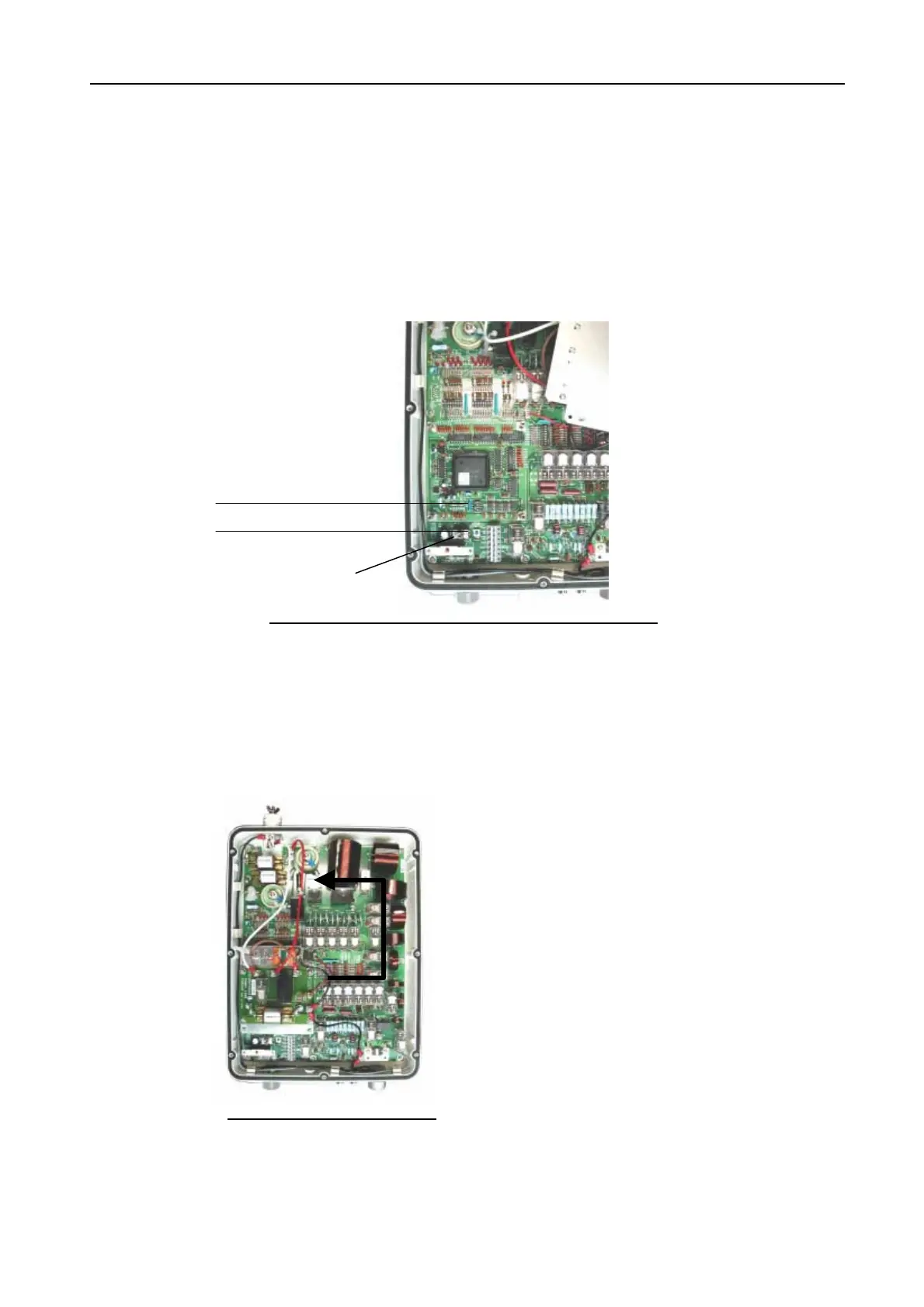
5. Relays are switched on/off in order as shown by the arrow in Fig.6.2.2. The test
result is displayed by LEDs.
6. Set the DIP switch, S2-#2 to OFF.
S3 (TUNE SW)
S2
Di
SW
Fig.6.2.1 COUP board with Dummy board removed
Fig.6.2.2 Order of relay test
1) When CR1 is on, built-in ROM of U1 is detective.
2) When CR2 is on, built-in RAM of U1 is detective.
3) When CR3 is on, built-in A/D converter of U1 is
detective. The matching circuit before the test is
selected when the test is complete.
S1
AUTO/MANUAL
 Loading...