5.2 Power supply unit
5-10
5.2.2 RELAY board (05P0744)
RELAY board consists of relay circuits, +12 V AVR and low/over voltage protectors.
When the transceiver unit is powered by 24 V, 12 V AVR, consisting of Q3 and CR8,
outputs +12 V to the power switch circuit in the No.1 controller. “POW ON” signal is
sent from CONT-1 board to U1, and Q4 and Q7 are driven to conduct.
Q7 is connected to inrush current limiters, CR2/Q1/R2 and CR1/Q2/R1, and Q4 to
relays, K1 and K2.
Q4 is connected to U1 via the delay circuit, R8 and C9, so that relays are on after inrush
current suppression. Thus, the relay contact failure will not result.
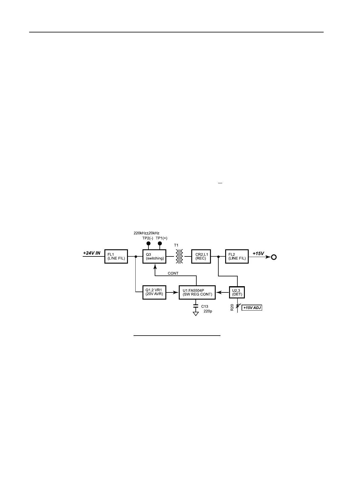
5.2.3 SW REG board (05P0737)
SW REG board consists of the switching regulator circuit and 20 V AVR consisting of
Q1, Q2 and VR1. The switching frequency of 220 kHz+20 kHz is adjusted by C13
connected to U1. Test points TP1 (+) and TP2 (-) are used to measure the switching
frequency. The switching regulator outputs +15 V, 3 A (typical) in about 70 %
efficiency. R20 adjusts +15 V.
Fig.5.2.2 SW REG (05P0737)
 Loading...