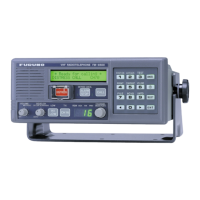
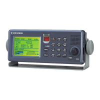
5.3 T-CPU board (05P0732)
5-21
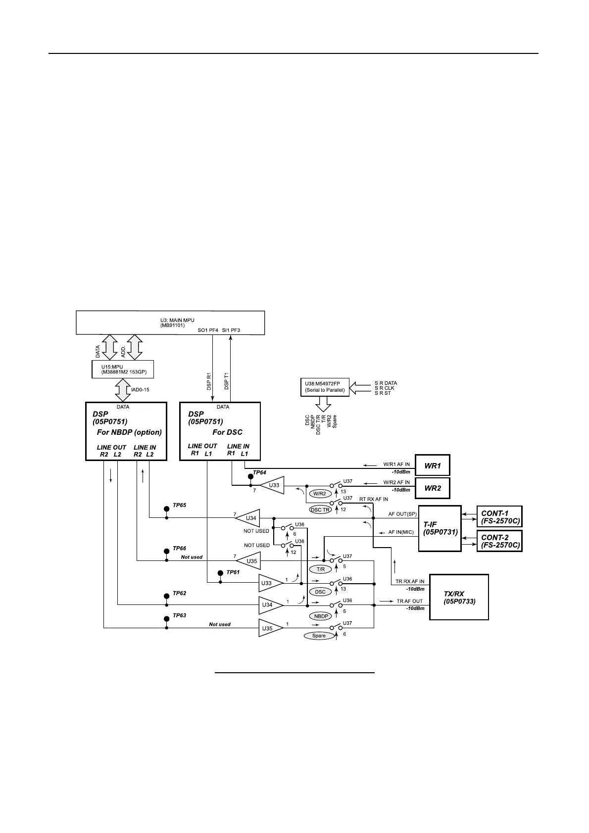
5.3.5 Digital Signal Processor (DSP)
Fig.5.3.4 shows the DSP input/output circuits.
DSP (05P0751) board for NBDP and DSC are the same in hardware, but different in
software. The LINE signals (AF) are switched by the analog switches. DSC distress
and safety receiver (W/R 1) is directly connected to DSP board for continuous watch.
The DSC general frequency signal is supplied to the DSP from either W/R 2 or TX/RX
board depending on the presence of the INST signal from W/R 2 board. The MIC signal
(AF-IN) from T-IF board is sent to TX/RX board through the analog switch T/R. The
MIC signal connected to NBDP DSP is for future use.
Fig.5.3.4 DSP input/output circuit
Communication for DSP-MAIN CPU
· DSC: Serial
· NBDP: Parallel
 Loading...