5.8 Antenna coupler, AT-1560
5-46
5.8 Antenna coupler, AT-1560
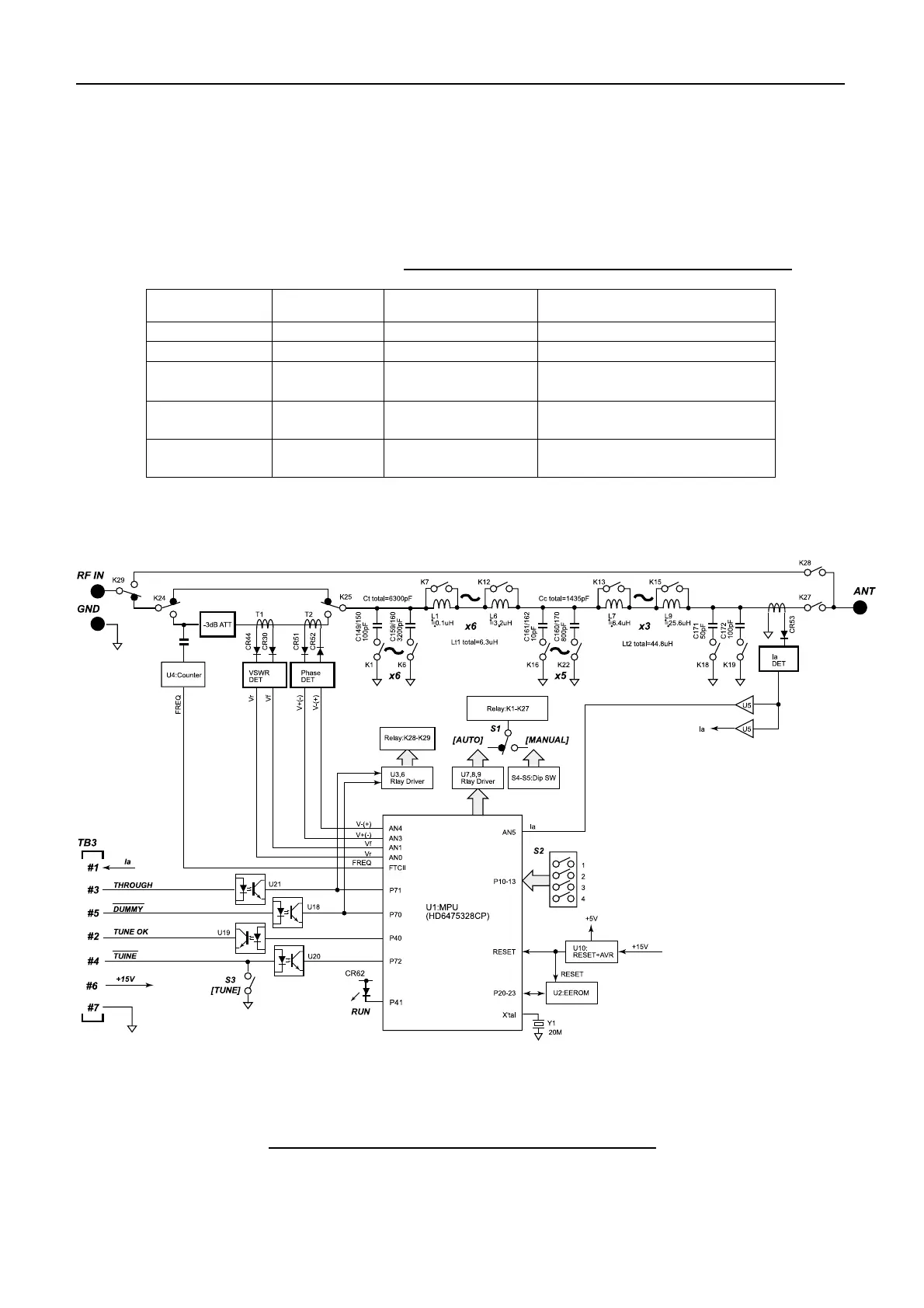
Fig.5.8.1 shows the block diagram of COUP board in antenna coupler, AT-1560. There
are two antenna couplers as shown in Table 5.8.1.
Table 5.8.1 Comparison between Antenna couplers
AT-1560-15 AT-1560-25 Remarks
Used by FS-1570 FS-2570/FS-1570
Input power 150W 250W
Dummy load
10Ω+250P
(100W)
10Ω+250P
(200W)
Dummy board 05P0543 05P0610
Antenna is grounded through
this board when power is off.
COUP board 05P0528 05P0528A
In AT-1560-25, L8 and L9 are
switched by a reed relay.
Fig.5.8.1 Block diagram of COUP board (05P0528)
 Loading...