AV-300i Version 2 User’s Guide
—————— Function Description ——————
Ch.1
17
Chapter 1 - FUNCTION DESCRIPTION
1.1 GENERAL CONSIDERATIONS
The drive control diagram is made of functional Blocks each representing a part of the total function. For
example speed regulator, ramp etc., each containing some Variables, the gains, the ramp times, the limits etc.
The input and / or output of Blocks are interconnected to make the complete system function. Such interconnec-
tions are called SIGNALS.
The setting of the Drive parameters/variables can be performed via the keypad or a PC Configurator.
The structure of the menu functions is the following:
src (Source) These are parameters that select where an input comes from. The
selections are from a pick-list.
The source is aimed at controlling (or enabling) the Block inputs.
cfg (Configuration) These are parameters that define how the function or parameter acts. For
example: Ramp times, internal references adjustments.
mon (Monitor) Signals in this menu are variables. They are read only, and show the value or
state of a signal.
The three above elements are inside a menu, as needed by each single Block.
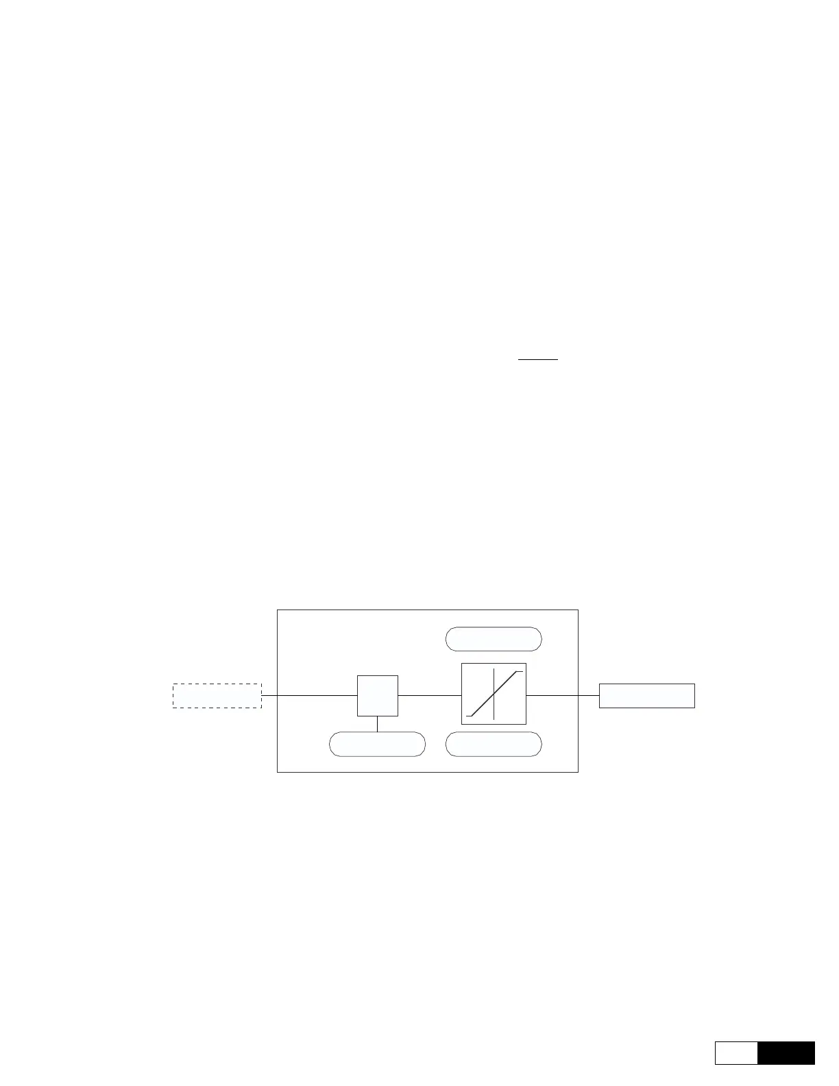
Example Block:
An out 1 src
X
An out 1 lo lim
An out 1 hi lim
An out 1 scale
An out 1 mon
Input selected
X
Parameter
Parameter
Parameter
Variable
cfg
src mon
This chapter describes:
· Variable connection methods
· Block functions
· Signal normalization

 Loading...


