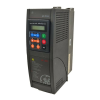
AV-300i Version 2 User’s Guide
—————— Function Description ——————
Ch.1
25
1.2 DRIVE STATUS MENU (STATUS)
This menu displays a series of variables useful to check the Drive state.
The variable function is clearly explained by the variable name.
In case it is needed, a short explanation is added.
Some variables are not applicable to all the different regulation modes.
In this case the display does not show the variable name but the writing N/A, “Not Available”.
The status variables are noted with a letter to show any ties to a specific regulation mode:
S Sensorless
F Field oriented
V V/f
If a variable is not available with a specific regulation mode, the system writes on its side the mode with which it
is active. Example: Torque ref [S, F], valid only with S and F.
1.2.1 Status
STATUS
Output voltage Voltage on the output terminals [ V ]
Output current Current on the output terminals [ A ]
Output power Power on the output terminals [ kVA ]
Torque ref[S, F] Torque reference on the motor [Nm]
Output frequency Output frequency [Hz]
Norm speed Motor speed [rpm]
Speed ref Motor speed reference [rpm]
Ramp ref Ramp Reference [rpm]
Enable SM mon It shows the Drive Enable state (1= on , 0 = off )
Start SM mon It shows the Drive Start state (1= on , 0 = off )
FastStop SM mon It shows the Drive Fast Stop state (1= on , 0 = off )
1.2.2 State of the Digital Inputs/Outputs (I/O Status)
Menu displays the state on the Drive Digital inputs and outputs, at the drive terminal points.
The first line shows the numbers of the digital I/Os.
The second line shows, under each number, the I/O state (0 or 1). The state detects the voltage presence (1) or absence (0).
‘E’ Enable terminal
‘A’ Terminal 10 Digital input 10
‘B’ Terminal 11 Digital input 11
‘X’ Expanded

 Loading...