AV-300i Version 2 User’s Guide
—————— Function Description ——————
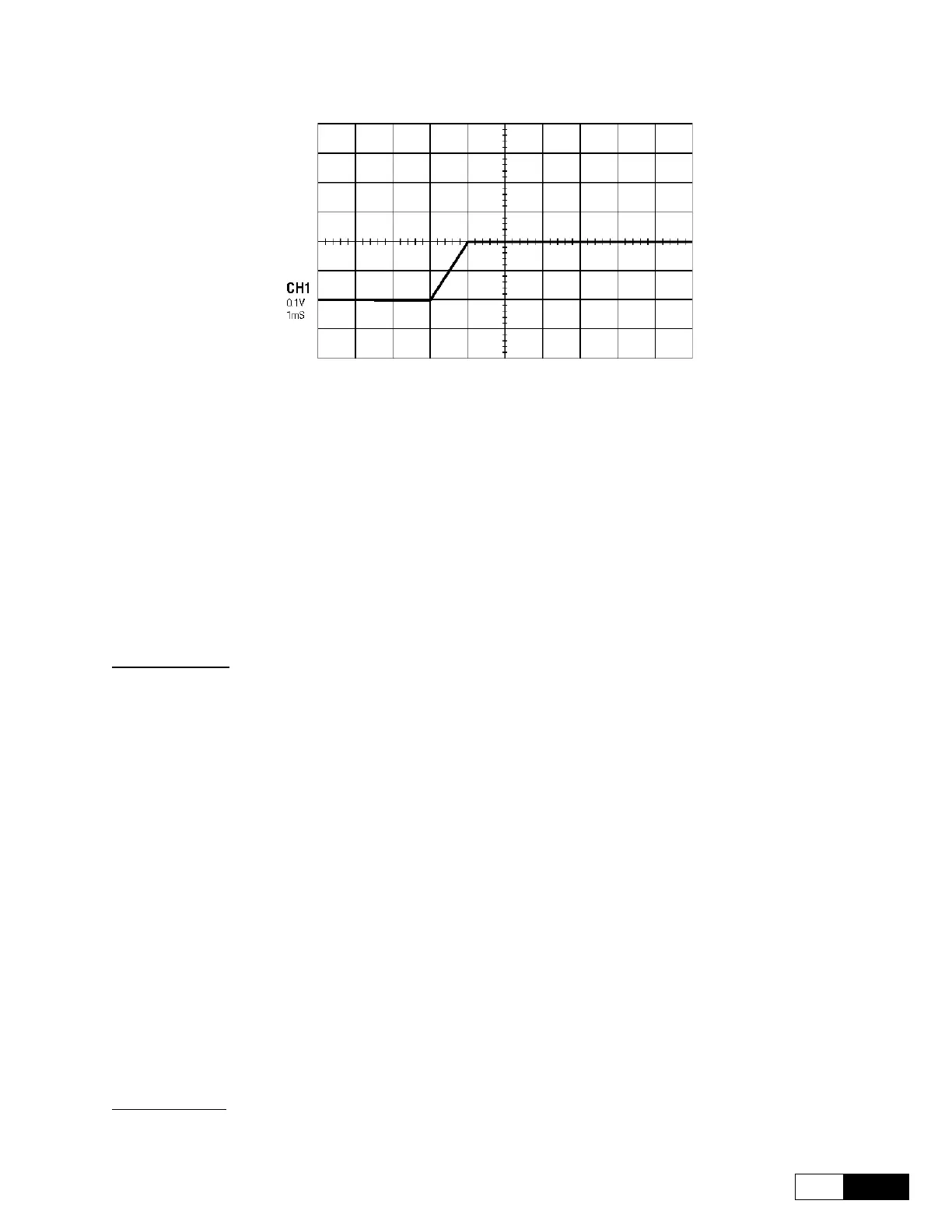
Ch.1
55
Figure 1.4.5.2.2: Optimal Output Current (Reaction Time @ 1ms) Displaying
1.4.5.3 Manual Tuning of the Flux Regulator
This tuning is necessary only with applications where the use of the field weakening is required.
Use a 2 channel digital scope.
In the I/O CONFIG/Analog outputs/Std analog outs menu set the analog outputs 1 & 2 (see
chapter 1.1 how to connect the variables):
- An out 1 src source connect the Flux ref variable
- An out 2 src source connect the Flux variable
On 21-22 terminals (see chapter 1.3 hardware manual) place channel 1 of the digital scope (CH1) on the Flux
ref (flux reference) signal; on 23-22 terminals place channel 2 (CH2) for the Flux signal (actual flux).
Disable the drive: press [O] key (red key) for 2 seconds.
In the TORQUE CONFIG/Zero torque cmd menu, set Zero torque cmd src = ONE.
In the REG PARAMETERS/Test generator menu to set the following parameters:
Test gen mode = Flux ref
Gen hi ref = Measured FluxNom · 16384 · √2
Gen low ref = Measured FluxNom · 0.8 · 16384 · √2
Gen period = 0.1 s
NOTE! Measured FluxNom is the nominal Flux value calculated by the drive during the “FluxReg
autotune”procedure; in the SETUP MODE/FluxReg autotune results it’s possible to
read this value.
In the REG PARAMETERS/Vlt regulator/Base values menu, set VltP base value parameter to its
max value. This value depends by the drive size. Pressing “Shift + Help” the max value is displayed.
In the REG PARAMETERS/Vlt regulator/Percent values menu, set VltP gain % parameter to
100%.
In the REG PARAMETERS/Flux regulator/Percent values, set to zero the FlxP gain % &
FlxI gain % parameters.
Enable the drive:
make sure that terminal 12 is active (+24V) and press [I] key (green key). On the channel CH1 the Flux ref will
be displayed; on the channel CH2 the Flux signal will be displayed (see figure: 1.4.5.3.1).

 Loading...


