AV-300i Version 2 User’s Guide
—————— Block Diagrams ——————
Ch.2
203
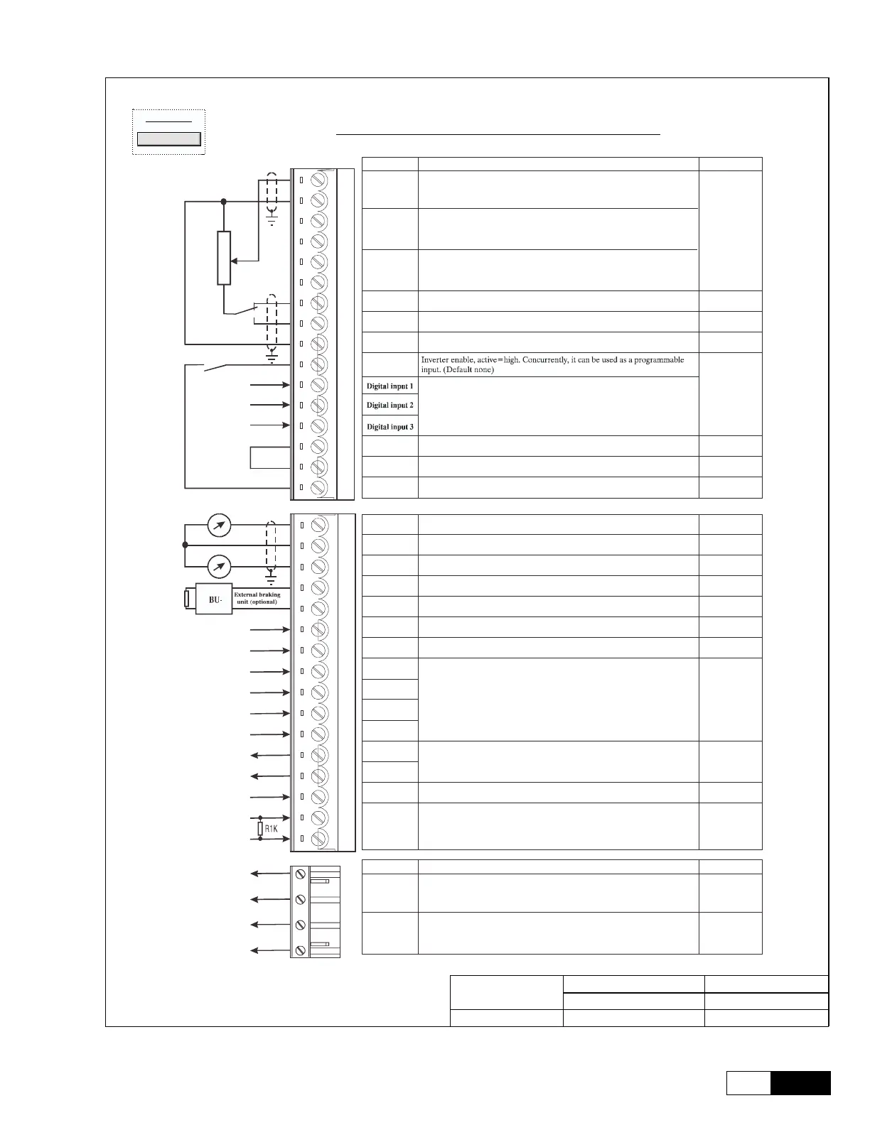
TERMINAL BOARD LAYOUT DRAWING
IO
Back
NAVIGATION
TB_Layout.vsdAV-300i AC flux vector Drive
10/15/99 -- RM
File name:
Issued Date
Initials:
Revision Date
GE Industrial Systems
Salem, Va. USA
Proprietary Information
Do Not Copy
PRODUCT:
03/02/00 -- RNC
ABCDE FGH I J K LMNOP
01
02
03
04
05
06
07
08
09
10
11
12
13
14
15
16
17
18
19
20
ABCDE FGH
01
02
03
04
05
06
07
08
09
10
11
12
13
14
15
16
17
18
19
20
21
1
2
3
4
5
6
7
8
9
12
13
14
15
16
18
19
Strip X1
Function max
Programmable/configurable analog differential input. Signal: terminal 1.
Reference point: terminal 2. Default setting: Ramp ref 1
±10V
Programmable/configurable analog differential input. Signal: terminal 3. 0.25mA
Reference point: terminal 4. Default setting: none (20mA when
Programmable/configurable analog differential input. Signal: terminal 5.
current loop
input)
Reference point: terminal 6. Default setting: none. (1)
+10V
Reference voltage +10V; Reference point: terminal 9 +10V/10mA
-10V
Reference voltage -10V; Reference point: terminal 9 -10V/10mA
0V
Internal 0V and reference point for±10V -
Enable/
Digital input 0
+30V
3.2mA @ 15V
5mA @ 24V
Programmable inputs,
Default=none
6.4mA @ 30V
COM D I/O
Reference point for digital inputs and outputs,term.12...15, 36...39, 41...42
-
0V24
Reference point for + 24V OUT supply, terminal 19 -
+24V OUT
+24V supply output. Reference point: terminal 18 or 27 or 28
+22 28V
120mA @ 24V
Analog input 1
Analog input 2
Analog input 3
Analog output
1
Program.analog output; def.setting: none
±10V/5mA
0V
Internal 0V and reference point for terminals 21 and 23
-
Analog output
2
Program.analog output; def.setting: none
±10V/5mA
BU comm.
output
VeCon controlled BU-32 braking units command. Ref. point: term.27.
+28V/15mA
0V24
Reference point for BU-32 command, terminal 26
-
RESERVED -
Digital input 4 +30V
Digital input 5 3.2mA @ 15V
Digital input 6 5mA @ 24V
Digital input 7 6.4mA @ 30V
Digital output
2
+30V/40mA
Digital output
3
Supply D O
Supply input for digital outputs on terminals 41/42. Ref. point: term.16.
+30V/80mA
Motor PTC 1.5mA
Programmable digital outputs; default setting: none
Motor PTC sensing for overtemperature (cutoff R1k if used)
Programmable digital inputs; default setting: none
21
22
23
26
27
28
29
36
37
38
39
41
42
46
78
79
Strip X2 Function Max.
250V AC
1A
250V AC
1A
Digital output 0
Relay
Potential- free relay contact, programmable output,
Default=Drive OK when closed
80
82
83
85
RESERVED
Digital output 1
Relay
Potential- free relay contact, programmable output,
Default=Speed is zero when closed

 Loading...


