5-14 PQM Power Quality Meter GE Power Management
5.2 A1 METERING 5 MONITORING
5
5.2.6 DEMAND
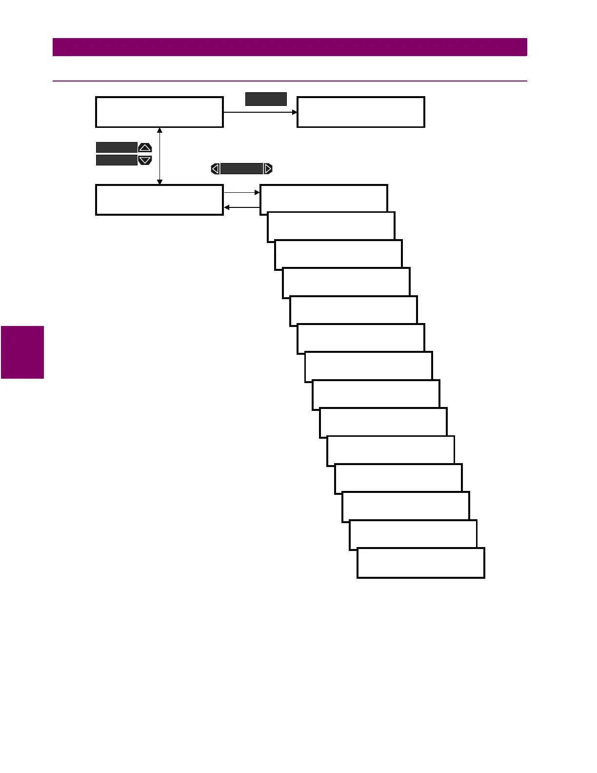
Figure 5–8: ACTUAL VALUES PAGE 1 – METERING / DEMAND
PHASE A/B/C/NEUTRAL DEMAND:
This message displays the phase A/B/C/N current demand (in Amps)
over the most recent time interval.
3
Φ
REAL POWER DEMAND:
This message displays the 3 phase real power demand (in kW) over the most
recent time interval.
3
Φ
REACTIVE POWER DEMAND:
This message displays the 3 phase reactive power demand (in kvar) over
the most recent time interval.
]] ACTUAL VALUES
]] A1 METERING
] DEMAND
]
PHASE A CURRENT
DEMAND = 125 A
PHASE B CURRENT
DEMAND = 125 A
PHASE C CURRENT
DEMAND = 125 A
NEUTRAL CURRENT
DEMAND = 25 A
]] ACTUAL VALUES
]] A2 STATUS
ACTUAL
3
Φ
ΦΦ
Φ
REAL POWER
DEMAND = 1000 kW
3
Φ
ΦΦ
Φ
REACTIVE POWER
DEMAND = 25 kvar
3
Φ
ΦΦ
Φ
REAL APPARENT
DEMAND = 1007 kVA
Ia MAX DMD = 560 A
12:00:00am 01/01/95
Ib MAX DMD = 560 A
12:00:00am 01/01/95
Ic MAX DMD = 560 A
12:00:00am 01/01/95
In MAX DMD = 560 A
12:00:00am 01/01/95
3
Φ
ΦΦ
Φ
kW MAX = 1000
12:00:00am 01/01/95
3
Φ
ΦΦ
Φ
kvar MAX = 25
12:00:00am 01/01/95
3
Φ
ΦΦ
Φ
kVA MAX = 1200
12:00:00am 01/01/95
MESSAGE
MESSAGE
MESSAGE

 Loading...


