EasyManua.ls Logo

GE Power Quality Meter Series User Manual

GE Power Quality Meter Series
282 pages
To Next Page IconTo Next Page
To Previous Page IconTo Previous Page
Page #162 background imageLoading...
Page #162 background image
6-16 PQM Power Quality Meter GE Power Management
6.6 POWER ANALYSIS 6 SOFTWARE
6
6.6.3 TRACE MEMORY
The trace memory feature allows the PQM to be setup to trigger on various conditions. The trace memory can
record maximum of 36 cycles of data (16 samples per cycle) for all voltage and current inputs simultaneously.
A Total Trace Triggers Counter has been implemented in the PQM Memory Map at Register 0x0B83. This reg-
ister will keep a running total of all valid Trace Memory Triggers from the last time power was applied to the
PQM. The Total Trace Triggers counter will rollover to 0 at 65536. The trace memory feature is implemented
into PQMPC as shown below.
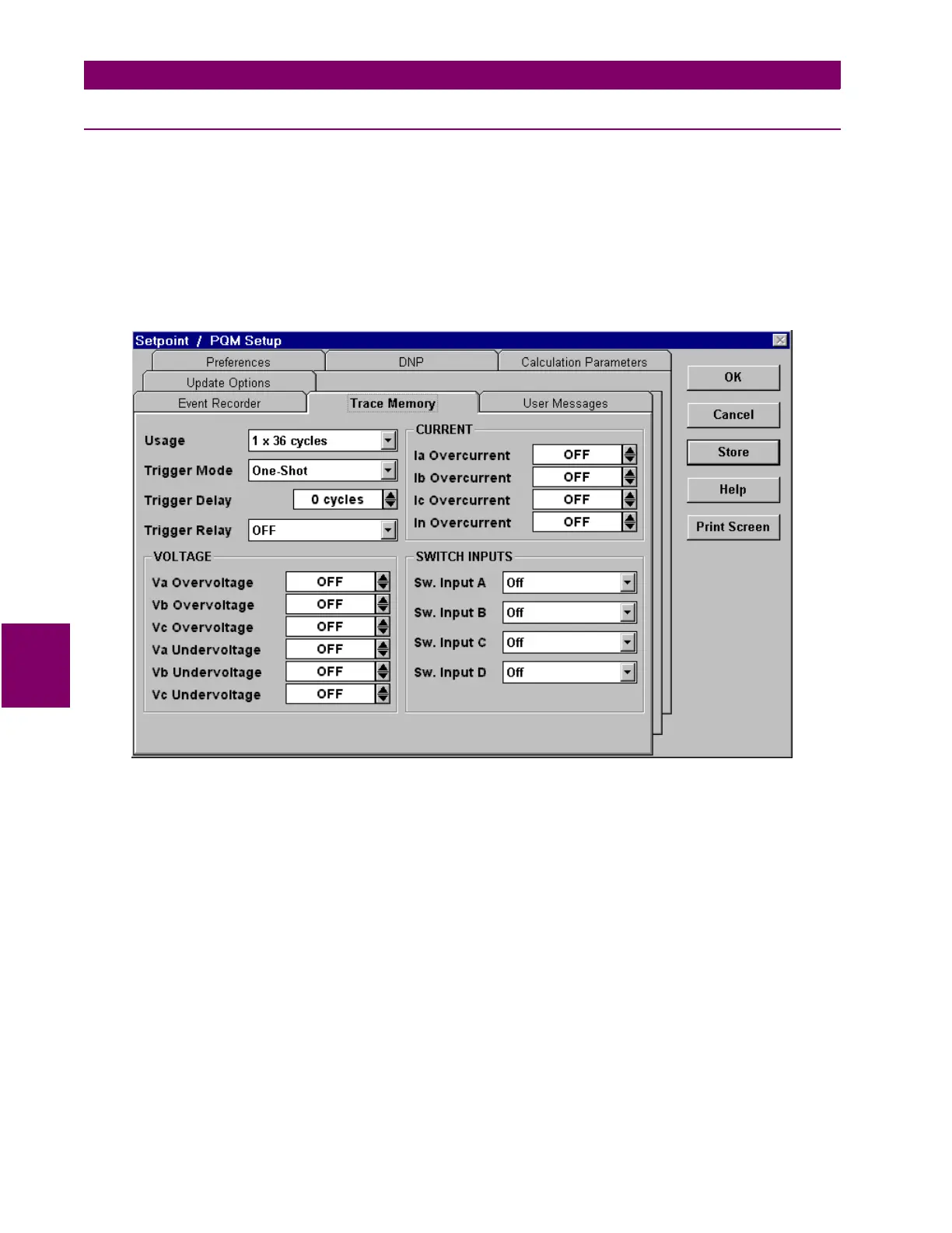
1. Select the
Setpoint > PQM Setup
menu item to setup the trace memory feature. This launches the PQM
Setup dialog box shown below. Click on the
Trace Memory
tab to display the trace memory parameters.
The
Memory Usage
is set as follows:
1 x 36 cycles
: upon trigger, the entire buffer is filled with 36 cycles of data
2 x 18 cycles
: 2 separate 18-cycle buffers are created and each is filled upon a trigger
3 x 12 cycles
: 3 separate 12 cycle buffers are created and each is filled upon a trigger
If the
Trigger Mode
is set to
One-Shot
, then the trace memory is triggered once per buffer; if it is set to
Retrig-
ger
, then it automatically retriggers and overwrites the previous data.
The
Trigger Delay
delays the trigger by the number of cycles specified.
The
VOLTAGE
,
CURRENT
, and
SWITCH INPUTS
selections are the parameters and levels that are used to trig-
ger the trace memory.
Clicking
Store
sends the current settings to the PQM.

Table of Contents

Question and Answer IconNeed help?

Do you have a question about the GE Power Quality Meter Series and is the answer not in the manual?

GE Power Quality Meter Series Specifications

General IconGeneral
BrandGE
ModelPower Quality Meter Series
CategoryMeasuring Instruments
LanguageEnglish

Summary

1.2 STANDARD FEATURES

1.3 SPECIFICATIONS

1.3.1 PQM SPECIFICATIONS

Technical specifications for current inputs, voltage inputs, sampling modes, and relays.

2 INSTALLATION

2.2 ELECTRICAL

Electrical connection details for various system configurations.

2.2.1 EXTERNAL CONNECTIONS

Details on terminal connections for VT, control power, CT, and signal wiring.

2.2.5 OUTPUT RELAYS

Configuration and operation of alarm and auxiliary output relays.

2.2.6 SWITCH INPUTS (OPTIONAL)

Information on programmable switch inputs and their assignable functions.

2.2.7 ANALOG OUTPUTS (OPTIONAL)

Details on analog output configuration for transducer interface and PLC connection.

2.2.9 RS485 SERIAL PORTS

Guidelines for connecting and configuring RS485 serial ports for communication.

3 OPERATION

3.3.9 SETPOINT ACCESS SECURITY

Software and hardware security features for protecting setpoint changes.

4 PROGRAMMING

4.1.1 SETPOINT ENTRY METHODS

Methods for entering setpoints via front panel, RS485, or RS232 ports.

4.2 S1 PQM SETUP

Configuration settings for the PQM, including preferences and communication ports.

4.2.3 SETPOINT ACCESS

How to enable and configure setpoint access using codes or switch inputs.

4.2.4 RS485/RS232 SERIAL PORTS

Configuration of communication ports, including Modbus address, baud rate, and parity.

4.3 S2 SYSTEM SETUP

System setup configuration for current, voltage, analog outputs, and inputs.

4.3.1 CURRENT/VOLTAGE CONFIGURATION

Configuring CT wiring, neutral sensing, VT wiring, and VT ratio.

4.3.2 ANALOG OUTPUTS (OPTIONAL)

Configuring analog outputs for transducer interface or PLC connection.

4.3.4 SWITCH INPUTS

Defining switch input names, functions, activation, and time delays.

4.3.5 PULSE OUTPUT

Configuring pulse output parameters for kWh, kvarh, kVAh, and pulse width.

4.4 S3 OUTPUT RELAYS

Configuration and operation of alarm and auxiliary output relays.

4.5 S4 ALARMS/CONTROL

Configuration of various alarms and control parameters for the PQM.

4.5.1 CURRENT/VOLTAGE ALARMS

Settings for current and voltage alarms, including under/over levels and delays.

4.5.2 TOTAL HARMONIC DISTORTION

Configuration of alarms for average current and voltage THD levels and delays.

4.5.4 POWER ALARMS

Configuration of alarms for real, reactive, and apparent power levels.

4.5.5 POWER FACTOR

Settings for power factor lead and lag alarms, including pickup, dropout, and delay.

4.5.6 DEMAND ALARMS

Configuration of alarms for phase and 3-phase current, power, and demand levels.

4.6 S5 TESTING

Procedures for testing hardware components like relays and LEDs, and simulation modes.

4.6.1 TEST OUTPUT RELAYS & LEDS

Manually testing output relays and status indicators via keypad or serial port.

4.6.2 CURRENT/VOLTAGE SIMULATION

Forcing simulated currents and voltages for testing relay functions.

4.6.3 ANALOG OUTPUTS SIMULATION

Simulating analog outputs to test connections with programmable controllers.

5 MONITORING

5.2 A1 METERING

Display of metering values for current, voltage, power, frequency, and energy.

5.2.1 CURRENT

Displays phase currents, average values, and current unbalance.

5.2.2 VOLTAGE

Displays phase and line voltages, average values, and voltage unbalance.

5.2.4 POWER

Displays real, reactive, apparent power, and power factor for phases and three-phase.

5.2.5 ENERGY

Displays accumulated energy values (kWh, kvarh, kVAh) and energy costs.

5.2.6 DEMAND

Displays current and power demand values over the most recent time interval.

5.3.1 ALARMS

Lists all active alarms, including current, voltage, power, and frequency alarms.

5.4 A3 POWER ANALYSIS

Analysis of power quality parameters, including crest factor and harmonics.

5.4.1 POWER QUALITY

Displays crest factor and transformer harmonic derating factor.

5.4.2 TOTAL HARMONIC DISTORTION

Displays calculated total harmonic distortion for currents and voltages.

6 SOFTWARE

6.2 PQMPC INSTALLATION

Procedure to check if PQMPC needs to be installed or upgraded.

6.2.2 INSTALLING/UPGRADING PQMPC

Minimum system requirements and steps for installing or upgrading PQMPC.

6.2.3 CONFIGURING PQMPC COMMUNICATIONS

Steps to establish communication between PQMPC and the PQM.

6.4 UPGRADING FIRMWARE

Procedures for upgrading PQM firmware using the latest files.

6.4.3 LOADING NEW FIRMWARE INTO THE PQM

Steps to load new firmware files into the PQM using PQMPC.

6.4.4 LOADING SAVED SETPOINTS INTO THE PQM

Loading existing setpoint files into the PQM and matching firmware versions.

6.5.1 ENTERING SETPOINTS

Illustrates entering setpoints using PQMPC's System Setup interface.

6.6 POWER ANALYSIS

Performing waveform capture and harmonic analysis using PQMPC.

6.6.1 WAVEFORM CAPTURE

Capturing and displaying voltage and current waveforms for analysis.

6.6.2 HARMONIC ANALYSIS

Performing harmonic analysis to identify issues caused by non-linear loads.

7 MODBUS COMMUNICATIONS

7.1.1 MODBUS PROTOCOL

Details on the Modbus RTU serial communication standard and PQM interface.

7.2 MODBUS FUNCTIONS

Details on Modbus function codes supported by the PQM for data access and control.

7.2.2 FUNCTION CODES 03/04 – READ SETPOINTS/ACTUAL VALUES

Modbus implementation for reading setpoints and actual values.

7.3 MODBUS MEMORY MAP

Detailed memory map of PQM registers for setpoints, actual values, and commands.

7.3.3 PQM MEMORY MAP

Detailed memory map of product information and commands.

8 DNP COMMUNICATIONS

8.1 DNP 3.0 PROTOCOL

Overview of the DNP 3.0 protocol and its implementation for the PQM.

9 COMMISSIONING

9.1 COMMISSIONING

Overview of the commissioning process for PQM setpoints.

APPENDIX C

C.1 PQM WARRANTY

GE Power Management relay warranty terms and conditions.

Related product manuals