5-26 PQM Power Quality Meter GE Power Management
5.4 A3 POWER ANALYSIS 5 MONITORING
5
PHASE A/B/C/N CURRENT THD:
These messages display the calculated total harmonic distortion for each
current input.
VOLTAGE Van/Vbn/Vcn/Vab/Vbc THD:
These messages display the calculated total harmonic distortion for
each voltage input. Phase to neutral voltages will appear when the setpoint
S2 SYSTEM SETUP \ CURRENT/
VOLTAGE CONFIGURATION \ VT WIRING
is stored as
WYE
. Line to line voltages will appear when the setpoint
S2 SYSTEM SETUP \ CURRENT/VOLTAGE CONFIGURATION \ VT WIRING
is stored as
DELTA
.
Ia/Ib/Ic/In MAX THD:
The maximum total harmonic value for each current input and the time and date which
the maximum value occurred are displayed. The
S1PQMSETUP\CLEARDATA\CLEARMAXTHDVALUES
setpoint
clears this value.
Van/Vbn/Vcn/Vab/Vbc MAX THD:
These messages display the maximum total harmonic value for each volt-
age input and the time and date at which the maximum value occurred. The setpoint
S1 PQM SETUP \ CLEAR
DATA \ CLEAR MAX THD VALUES
is used to clear this value. Phase to neutral voltages will appear when the set-
point
S2 SYSTEM SETUP \ CURRENT/VOLTAGE CONFIGURATION \ VT WIRING
is set to
WYE
. Line to line voltages will
appear when the setpoint
S2 SYSTEM SETUP \ CURRENT/VOLTAGE CONFIGURATION \ VT WIRING
is set to
DELTA
.
5.4.3 DATA LOGGER
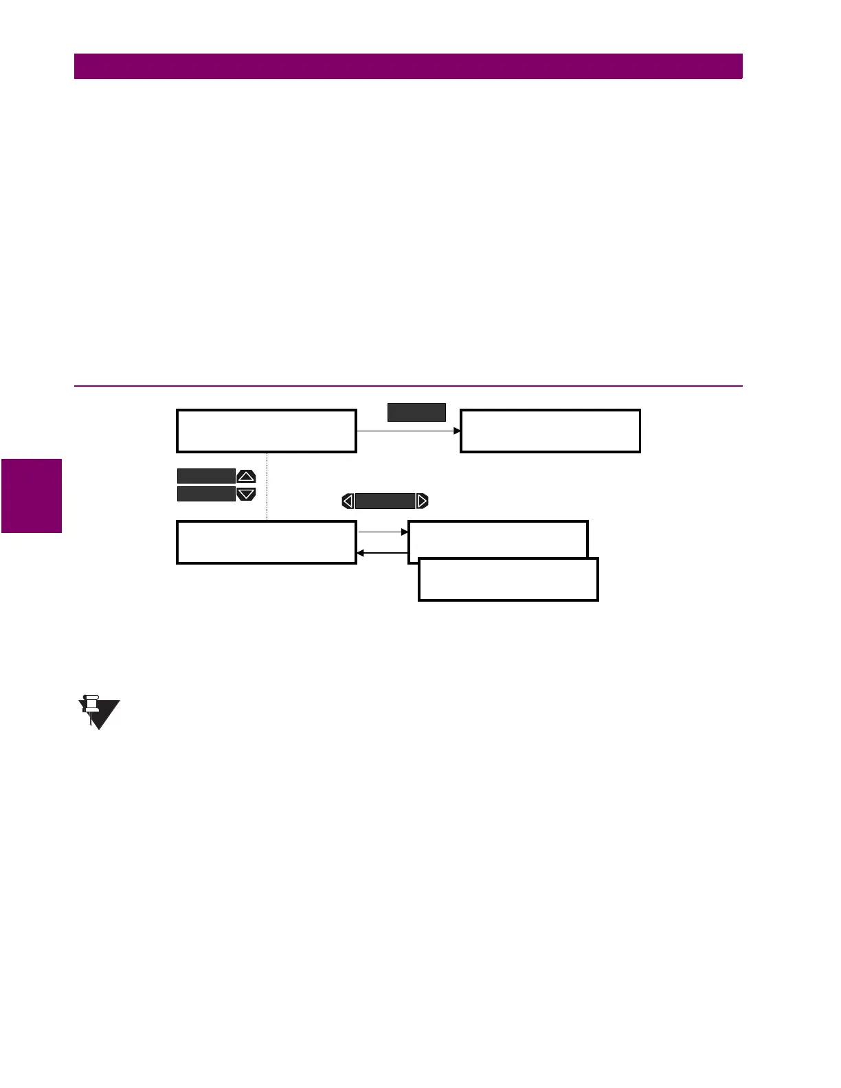
Figure 5–19: ACTUAL VALUES PAGE 3 – DATA LOGGER
DATA LOG 1:
This message display the current status of the Data Logger 1. The Data Logger can be set up
and run only from PQMPC. See Sections 6.6.4: DATA LOGGER on page 6–18 and A.1.6: DATA LOGGER
IMPLEMENTATION on page A–12 for a details on the Data Logger feature.
It is possible to stop the data logger from the PQM front panel using the
S2 SYSTEM SETUP/DATA LOG-
GER/STOP DATA LOGGER 1
setpoint.
DATA LOG 2:
See DATA LOG 1 description above and replace all references to DATA LOGGER 1 with DATA
LOGGER 2.
]] ACTUAL VALUES
]] A3 POWER ANALYSIS
] DATA LOGGER
]
DATA LOG 1: STOPPED
0% FULL
DATA LOG 2: STOPPED
0% FULL
]] ACTUAL VALUES
]] A4 PRODUCT INFO
ACTUAL
MESSAGE
MESSAGE
MESSAGE
NOTE

 Loading...


