2-4 PQM Power Quality Meter GE Power Management
2.2 ELECTRICAL 2 INSTALLATION
2
2.2 ELECTRICAL 2.2.1 EXTERNAL CONNECTIONS
Signal wiring is to Terminals 21 to 51. These terminals accommodate wires sizes up to 12 gauge.
Please note
that the maximum torque that can be applied to terminals 21 to 51 is 0.5 Nm (or 4.4 in ·lb.)
. CT, VT, and control
power connections are made using Terminals 1 to 20. These #8 screw ring terminals accept wire sizes as large
as 8 gauge. Consult the wiring diagrams for suggested wiring. A minimal configuration includes connections for
control power, phase CTs/VTs, and the alarm relay; other features can be wired as required. Considerations for
wiring each feature are given in the sections that follow.
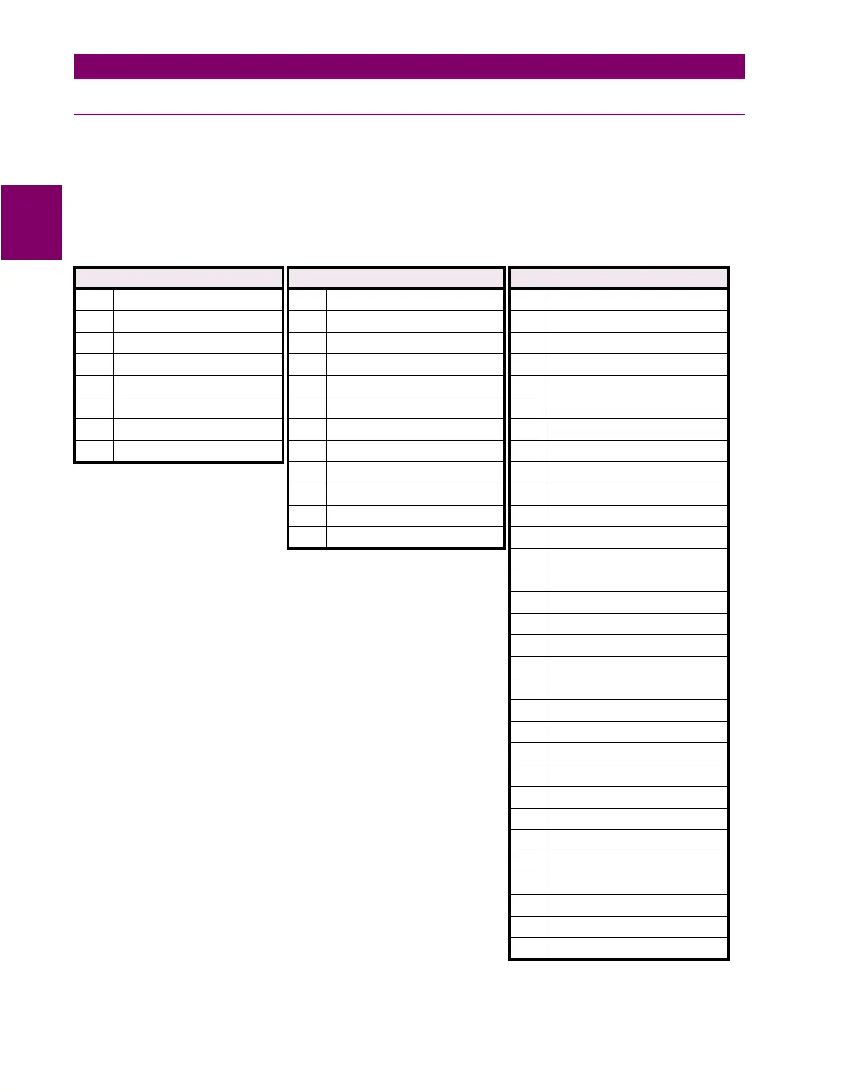
Table 2–2: PQM EXTERNAL CONNECTIONS
VT / CONTROL POWER ROW CT ROW SIGNAL UPPER ROW
1 V1 Voltage input 9 Phase A CT 5A 21 Analog shield
2 V2 Voltage input 10 Phase A CT 1A 22 Analog in –
3 V3 Voltage input 11 Phase A CT COM 23 Analog in +
4 Vn Voltage input 12 Phase B CT 5A 24 Analog out com
5 Filter ground 13 Phase B CT 1A 25 Analog out 4+
6 Safety ground 14 Phase B CT COM 26 Analog out 3+
7 Control neutral (–) 15 Phase C CT 5A 27 Analog out 2+
8 Control live (+) 16 Phase C CT 1A 28 Analog out 1+
17 Phase C CT COM 29 Switch 4 input
18 Neutral CT 5A 30 Switch 3 input
19 Neutral CT 1A 31 Switch 2 input
20 Neutral CT COM 32 Switch 1 input
33 +24 V DC switch com
34 Aux3 relay NC
35 Aux3 relay COM
36 Aux3 relay NO
37 Aux2 relay NC
38 Aux2 relay COM
39 Aux2 relay NO
40 Aux1 relay NC
41 Aux1 relay COM
42 Aux1 relay NO
43 Alarm relay NC
44 Alarm relay COM
45 Alarm relay NO
46 Comm 1 COM
47 Comm 1 –
48 Comm 1 +
49 Comm 2 COM
50 Comm 2 –
51 Comm 2 +

 Loading...


