A-10 PQM Power Quality Meter GE Power Management
A.1 PQM APPLICATION NOTES APPENDIX A
A
Any sample that deviates from its corresponding reference sample by the amount
V
k
2
for a minimum duration
as calculated above is detectable by the PQM.
EXAMPLE:
Consider a PQM with a nominal VT secondary voltage of 100V into the VT inputs. The trace memory trigger
for a Phase A undervoltage level of 90V is enabled with the following setpoints:
S2 SYSTEM SETUP \ CURRENT/VOLTAGE CONFIGURATION \ VT NOMINAL SECONDARY VOLTAGE:
100 V
S1 PQM SETUP \ TRACE MEMORY \ VA UNDERVOLTAGE TRIG LEVEL: 90%
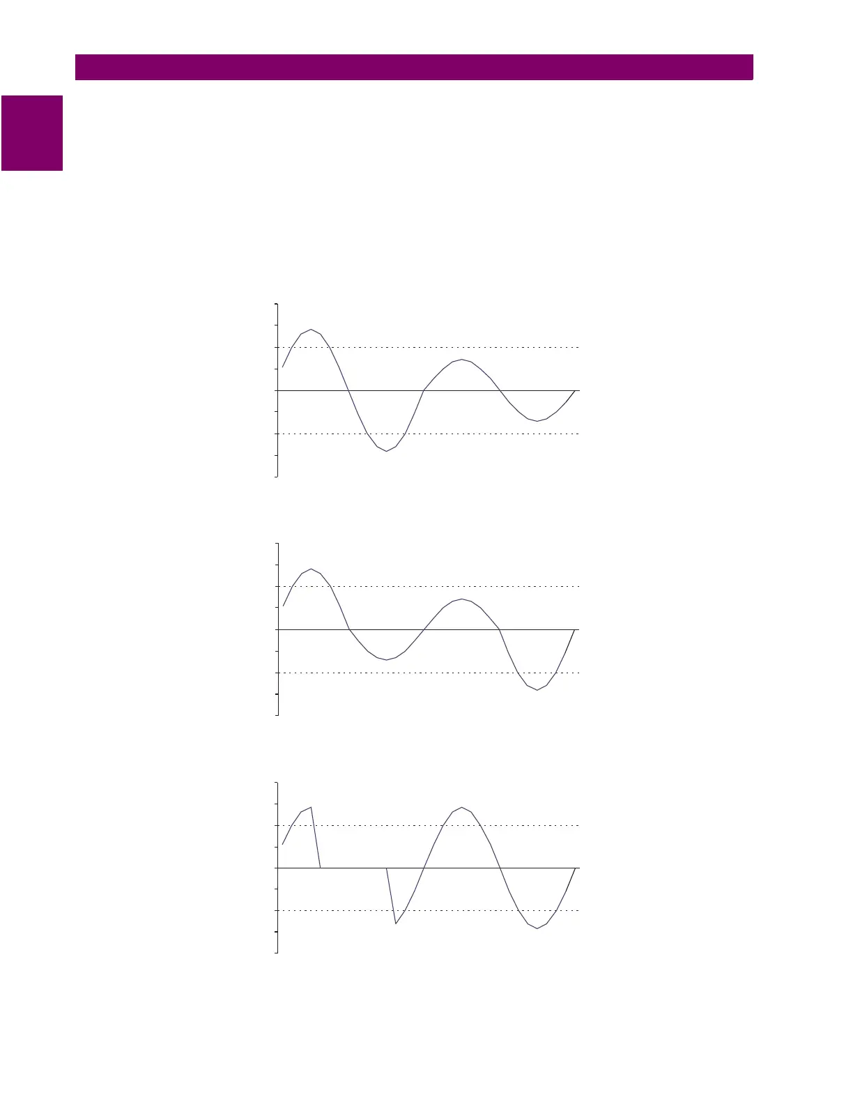
In the waveform below, an undervoltage fault occurs in the second cycle. The first cycle RMS voltage is 100V;
the second cycle RMS voltage is 50V, triggering the trace memory feature for the settings above.
A centered one cycle undervoltage fault is shown below. In this case, the first cycle RMS voltage is 79.05V
and the second cycle RMS voltage is 79.05V, triggering the trace memory feature for the settings above.
A half cycle undervoltage fault is shown below. In this case, the first cycle RMS voltage is 70.07V and the sec-
ond cycle RMS voltage is 100V, triggering the trace memory feature for the settings above.
–200
–150
–100
–50
0
50
100
150
200
–200
–150
–100
–50
0
50
100
150
200
–200
–150
–100
–50
0
50
100
150
200

 Loading...


