HEIDENHAIN iTNC 530 499
12.3 The PLANE function: Tilting the working plane (software option 1)
Defining the working plane with two vectors:
VECTOR PLANE
Application
You can use the definition of a working plane via two vectors if your
CAD system can calculate the base vector and normal vector of the
tilted machining plane. A normalized input is not necessary. The TNC
calculates the normal, so you can enter values between –99.999999
and +99.999999.
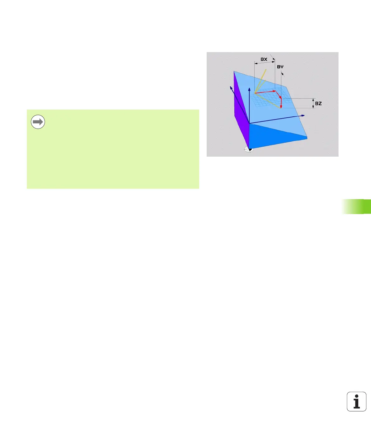
The base vector required for the definition of the machining plane is
defined by the components BX, BY and BZ (see figure at right). The
normal vector is defined by the components NX, NY, and NZ.
Before programming, note the following
The base vector defines the direction of the principal axis
in the tilted machining plane, and the normal vector
determines the orientation of the tilted machining plane,
and at the same time is perpendicular to it.
The TNC calculates standardized vectors from the values
you enter.
Parameter description for the positioning behavior: See
"Specifying the positioning behavior of the PLANE
function" on page 506.

 Loading...


