536 Programming: Execution of CAM Programs, Multi-axis Machining
12.7 Three-dimensional tool compensation (software option 2)
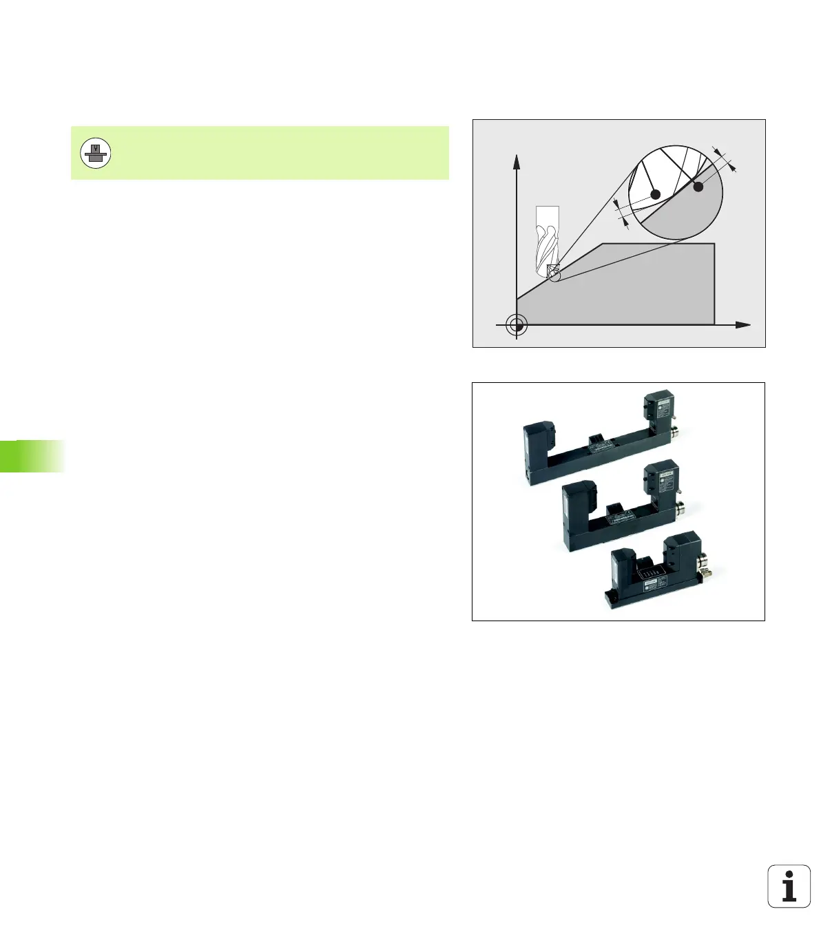
3-D tool radius compensation depending on the
tool’s contact angle (3D-ToolComp software
option)
The effective sphere radius of a radius cutter deviates from the ideal
form owing to the production process. The maximum form inaccuracy
is specified by the tool manufacturer; common error is between 0.005
and 0.01 mm.
The form inaccuracy can be determined with a laser system and the
corresponding laser cycles on the TNC. It can then be saved as a
compensation value table. This table contains angle values and the
deviation from the nominal radius R2 measured on the respective
angle value.
The 3D-ToolComp software option enables the TNC to compensate
the value defined in the compensation value table depending on the
actual contact point of the tool.
Requirements
Software option 3D-ToolComp is enabled
Software option 2, 3-D machining is enabled
MP7680, bit 6 must be set to the value 1: The TNC takes R2 from
the tool table into account during tool length compensation
The DR2TABLE column in the tool table (TOOL.T) is enabled
(MP7266.42)
The tool was measured with the laser system and the
compensation value table is available in a directory under TNC:\.
Alternatively you can also create the compensation table manually
(see "Compensation-value table" on page 537)
The tool dimensions L, R and R2 are entered in the tool table
(TOOL.T)
The path name of the compensation value table for the tool to be
compensated is entered (without file extension) in the DR2TABLE
column of the tool table (TOOL.T) (see "Tool table: Standard tool
data" on page 182)
NC program: NC blocks with surface normal vectors are required
(see "NC program" on page 539)
Software option 2 is also required to be able to use
software option 92, 3-D ToolComp.

 Loading...


