HEIDENHAIN iTNC 530 501
12.3 The PLANE function: Tilting the working plane (software option 1)
Defining the working plane via three points:
PLANE POINTS
Application
A working plane can be uniquely defined by entering any three points
P1 to P3 in this plane. This possibility is realized in the PLANE POINTS
function.
Before programming, note the following
The connection from Point 1 to Point 2 determines the
direction of the tilted main axis (X for tool axis Z).
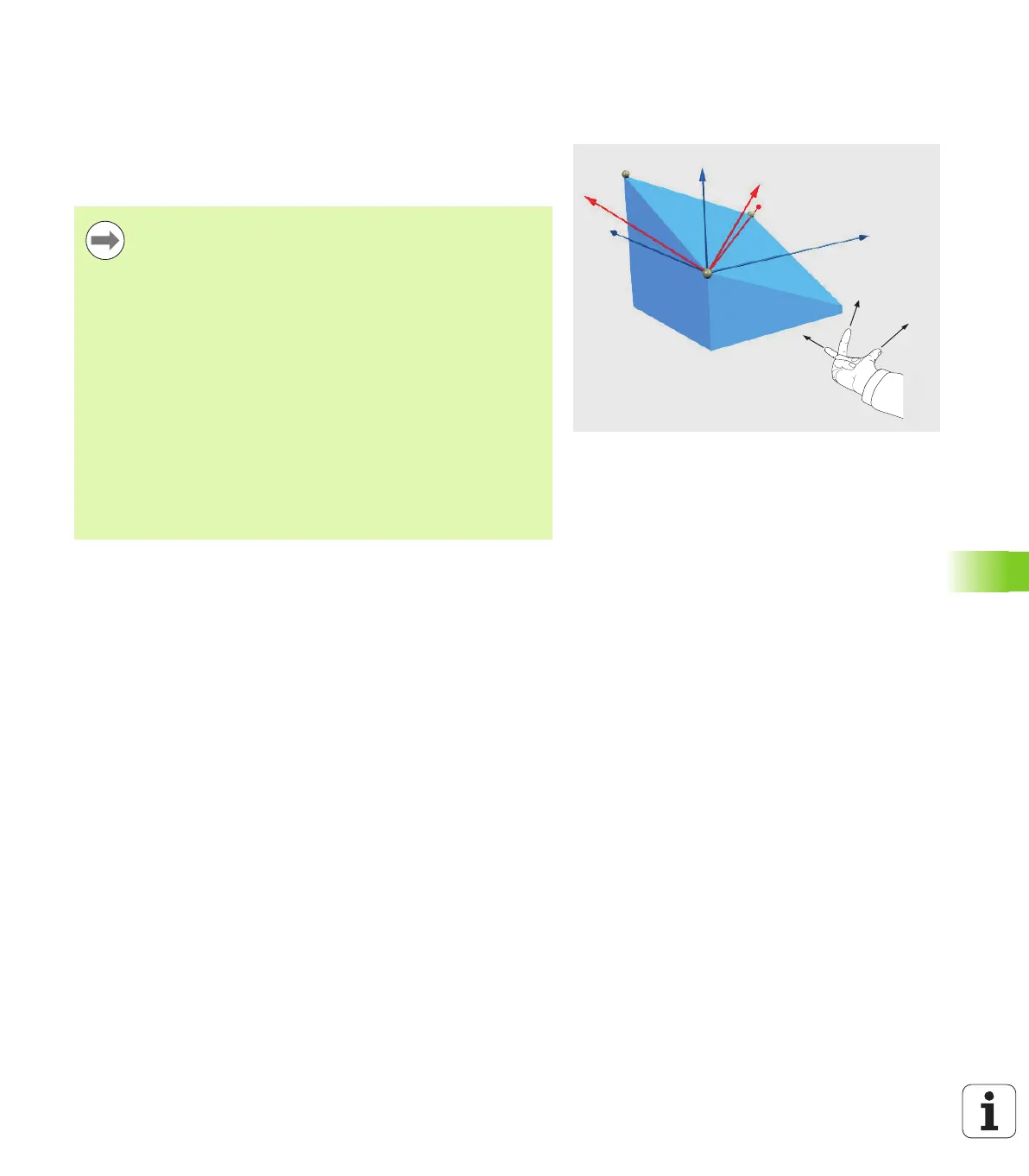
The direction of the tilted tool axis is determined by the
position of Point 3 relative to the connecting line between
Point 1 and Point 2. Use the right-hand rule (thumb = X
axis, index finger = Y axis, middle finger = Z axis (see
figure at right)) to remember: thumb (X axis) points from
Point 1 to Point 2, index finger (Y axis) points parallel to the
tilted Y axis in the direction of Point 3. Then the middle
finger points in the direction of the tilted tool axis.
The three points define the slope of the plane. The
position of the active datum is not changed by the TNC.
Parameter description for the positioning behavior: See
"Specifying the positioning behavior of the PLANE
function" on page 506.

 Loading...


