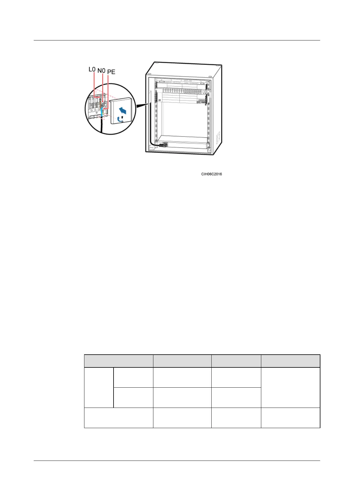
Figure 7-52 Installing a power cable for the AC heater
Step 3 Route and bind the cables. For details, see 7.5.1 Cabling Requirements.
Step 4 Label the installed cables. For details, see Attaching a Cable-Tying Label.
----End
7.4.5 (Optional) Installing an EMUA
This section describes the procedures for installing an EMUA and related cables in a TMC11H.
An EMUA can be installed in the reserved 1 U space in the TMC11H based on actual
requirements.
Prerequisite
The tools such as the screwdriver and ESD gloves are available.
Context
Table 7-4 describes the cables related to the EMUA.
Table 7-4 Cables related to the EMUA
Cable List
One End The Other End Remarks
Power
cable for
the
EMUA
RTN(+)
cable
M4 OT terminal Cord end
terminal
Black, 1.5 mm
2
, two
wires in black and
blue
NEG(-) cable M4 OT terminal Cord end
terminal
EMUA monitoring
signal cable
DB9 male connector RJ45 connector Black
DBS3900 (Ver.B)
Installation Guide
7 Outdoor Scenario with DC Power Supply (BBU Installed
in a TMC11H)
Issue 06 (2011-09-15) Huawei Proprietary and Confidential
Copyright © Huawei Technologies Co., Ltd.
181
 Loading...