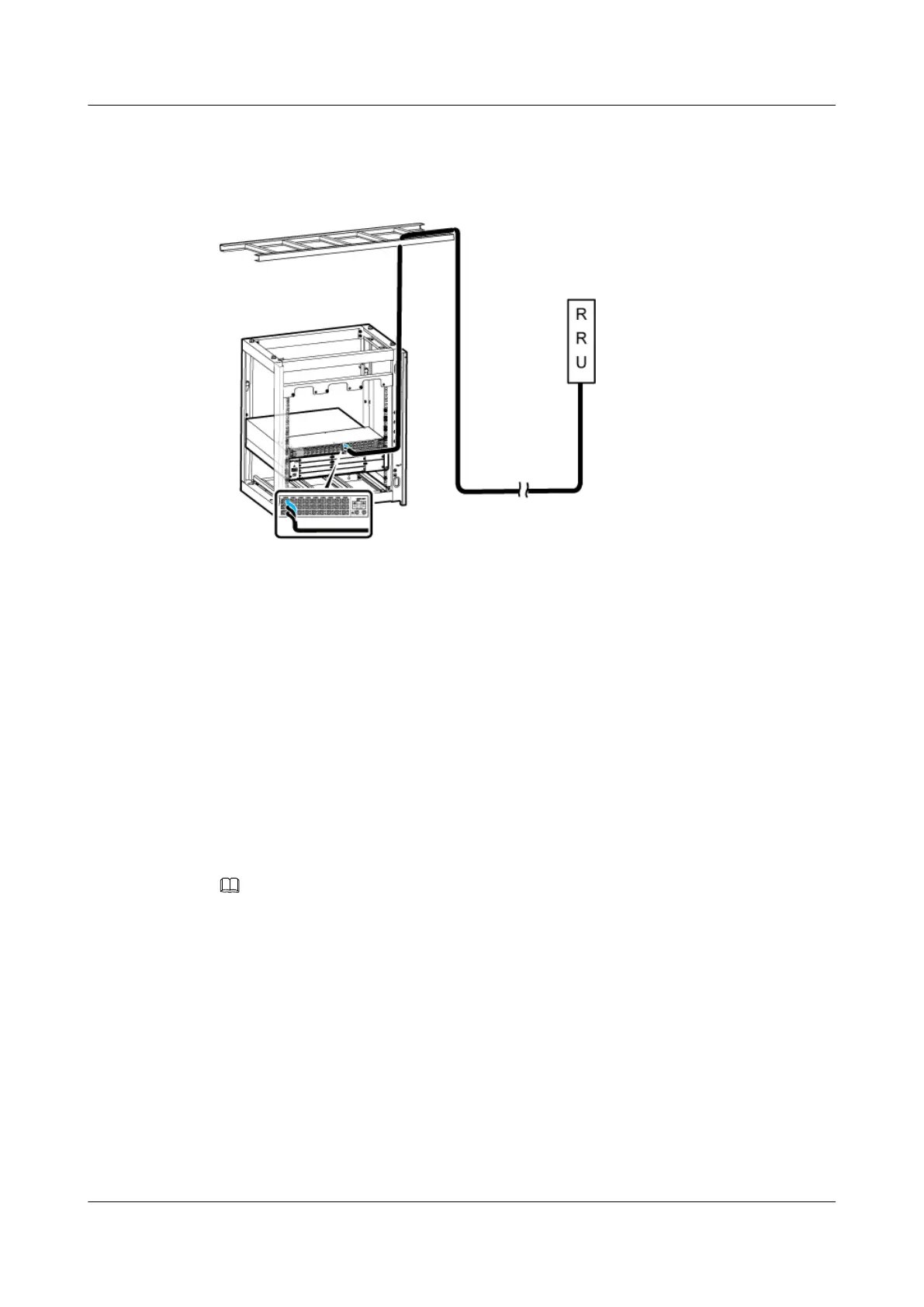
2. Connect the blue and black (or brown) wires at the other end to the wiring terminals labeled
NEG(-) and RTN(+) in the cabling cavity of the RRU respectively.
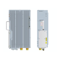
Figure 12-14 Installing an RRU power cable
Step 3 Route the cable by referring to 12.4.1 Cabling Requirements, and then use cable ties to bind
the cable.
Step 4 Label the installed cables by referring to Attaching a Sign Plate Label.
----End
12.4.4 Installing Transmission Cables
When a DBS3900 is deployed indoors with DC power supply, transmission cables such as E1/
T1 cables, FE/GE cables, and FE/GE optical cables must be installed based on onsite
requirements.
Context
NOTE
Install the transmission cables based on the connections of transmission cables. For details, see the
BBU3900 Hardware DescriptionTransmission Cable Connections.
Installing an E1/T1 Cable
An E1/T1 cable transmits E1/T1 signals between a BBU and external transmission equipment
when a DBS3900 is deployed indoors.
DBS3900 (Ver.B)
Installation Guide
12 Indoor Scenario with DC Power Supply (BBU Installed in
a 19-Inch Rack)
Issue 06 (2011-09-15) Huawei Proprietary and Confidential
Copyright © Huawei Technologies Co., Ltd.
419
 Loading...