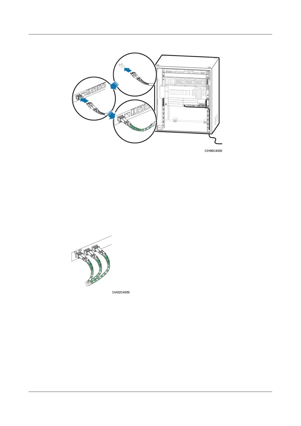
Figure 8-73 Installing a FE/GE optical cable
Step 3 Route the FE/GE optical cable along the cable trough on the right of the cabinet, and then use
cable ties to bind the cable.
Step 4 Route the cable by referring to 8.5.1 Cabling Requirements.
Step 5 Attach labels on the optical cable. For details, see Attaching a Sign Plate Label.
Step 6 Coil the optical fiber with winding plastic tape at the end connected to the BBU. The tape is
coiled between the optical connector and the first cable tie on the cabinet, as shown in Figure
8-74.
Figure 8-74 Coiling the optical fiber with winding plastic tape
----End
8.5.5 Installing Monitoring Signal Cables
When a DBS3900 is configured with one +24 V DC APM30H, you must install a monitoring
signal cable and in-position signal cable for the PSU (DC/DC).
Procedure
Step 1 Install a monitoring signal cable for the PSU (DC/DC), as shown in Figure 8-75.
1. Connect one end of the monitoring signal cable for the PSU (DC/DC) to the EXT_ALM0
port on the UPEU in the BBU.
DBS3900 (Ver.B)
Installation Guide
8 Outdoor Scenario with DC Power Supply (BBU Installed
in a +24 V DC APM30H)
Issue 06 (2011-09-15) Huawei Proprietary and Confidential
Copyright © Huawei Technologies Co., Ltd.
274
 Loading...